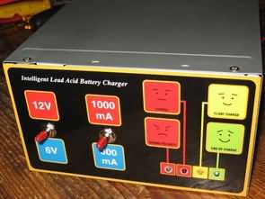
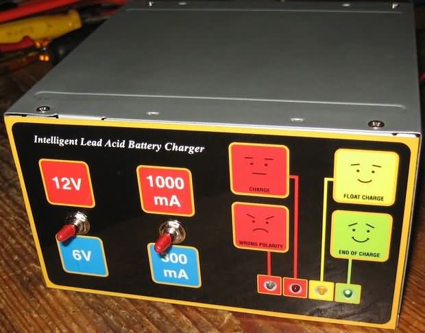
6V and 12V batteries battery charging circuit Charge Current is 0.3 A and 1A able to charge can be selected. Binding to have protection against battery reverse polarity. Float charging reverse connection, Charging status indicators and is equipped with
Float charger
the Float charger 14.7 V 12V battery is fully charged, the charging case feature becomes more of continuous battery life remains connected to the charging circuit if the charge voltage auto 13.6V battery charge voltage 7.35 V switches to a float charge Float charge 6.85
PCB dimensions to fit the computer’s power supply, it will be easy to boxing.
Smart Charger Circuit
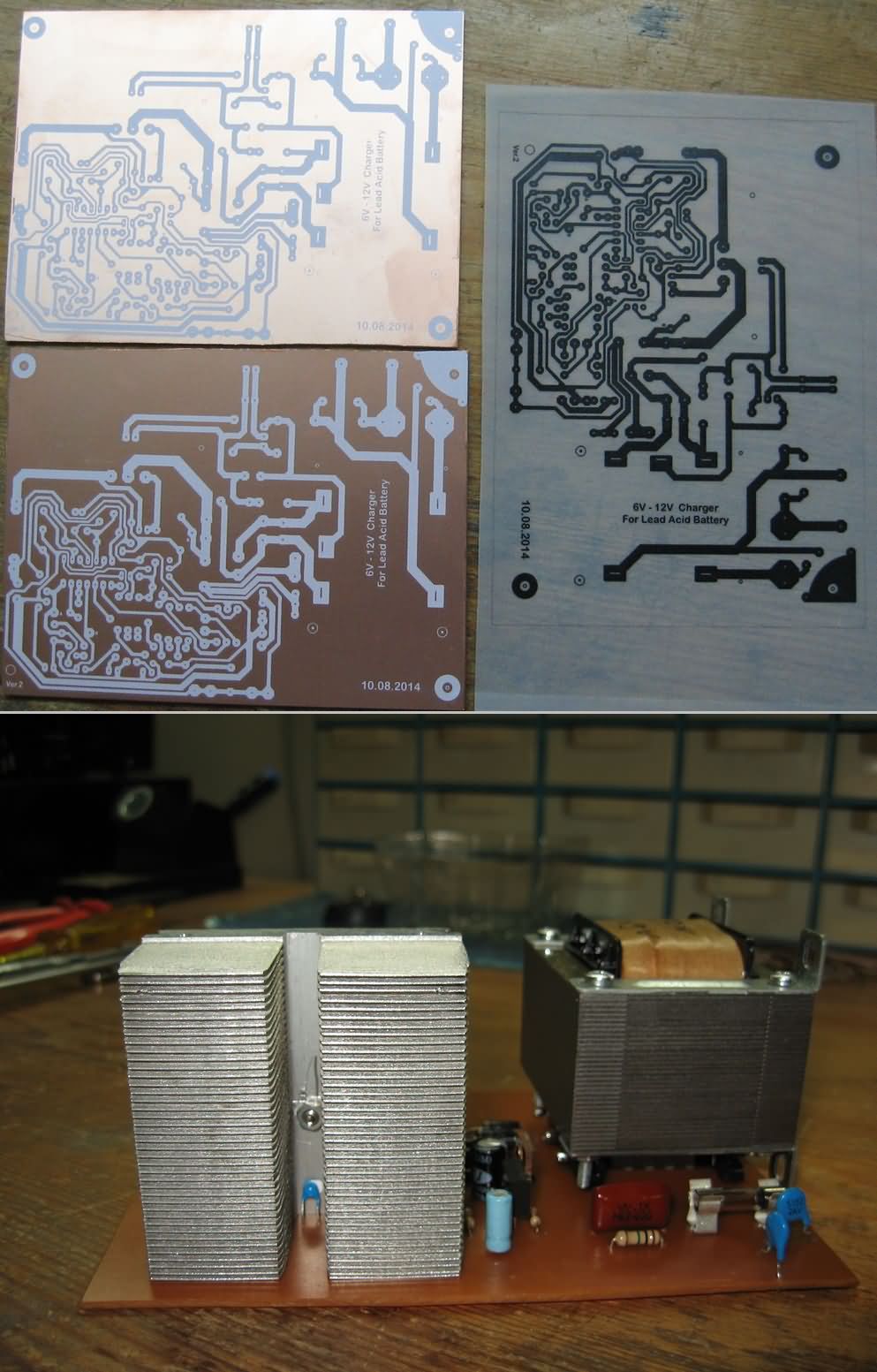
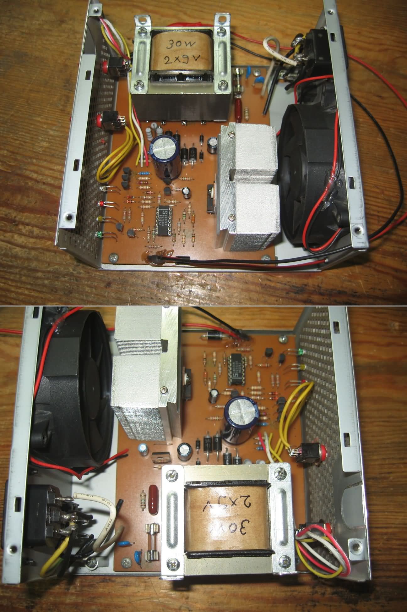
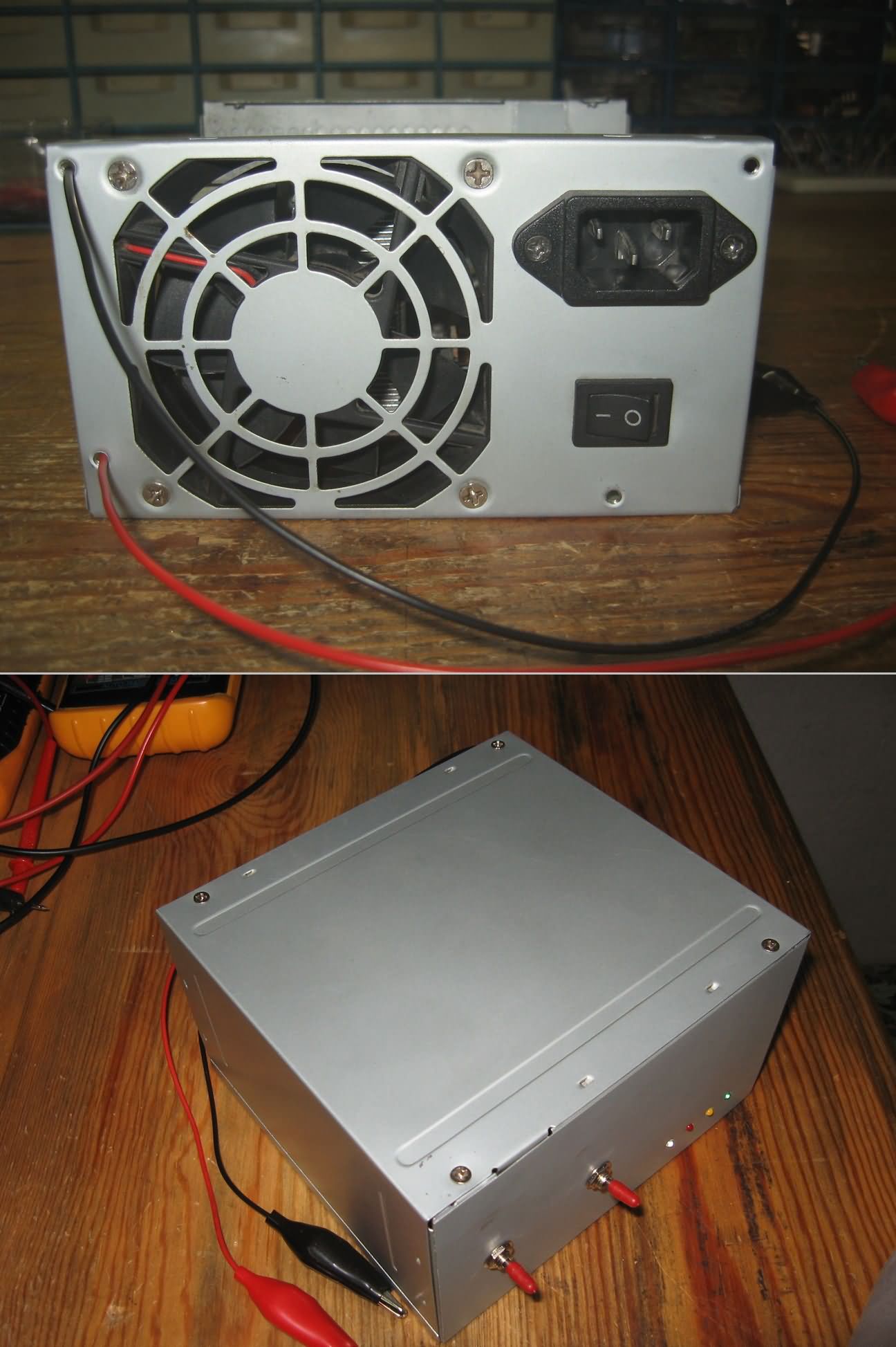
kit K8012 velleman the PSU and the PC in the box I tried make some changes to adapt. There are quite a few of these boxes in my hand, and we can supply almost everyone who wants to do out of the box very comfortable. I added heat set fan control circuit into the remaining space in the final stage.
Respect to the original documents of the circuit, especially some of the resistance 1% tolerance metal film to be asked. As you can select materials with very low tolerance.
Use a quality socket for the lm324. If necessary change would be a great convenience. Yellow and blue appear in a frame Assembly in the plan is completely up to you, even the parts that you have not made. Has nothing to do with the original version of those sections of the circuit.
Instead of the tip142 original or equivalent on the output that can be used mj3001 bdw83 already. TO3 sheathed element so that you can fit into the box I didn’t choose especially.
The original of the circuit in one non-A and b The points I made. Cable that passes between the legs of ICs and some subtle ways from the bottom to cancel (A A, B B) and I hooked some kalinlastirdim almost all ways. The resin melted in the surface of the copper plate I covered it with cellulose thinners even go overboard and take a walk all the way with the tip of the soldering iron and solder I covered.
I don’t recommend using solder paste leftovers in the long run not well cleaned because the oxidation is inevitable.
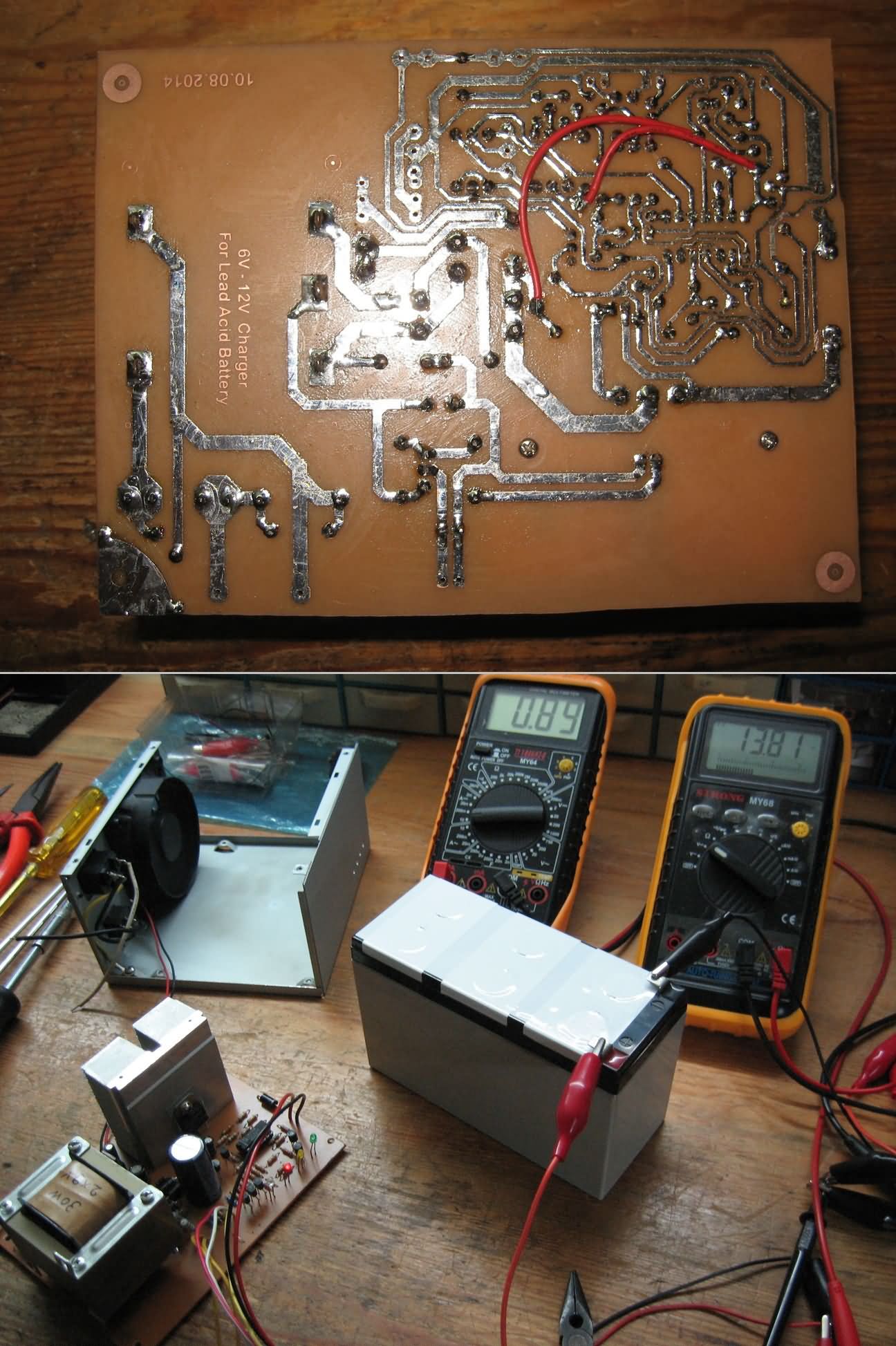
Current limits of the circuit of R29, R30, R31 do you determine with. A metal film made of them already to be. I put a film of carbon instead of metal film because I couldn’t find 1W. This low value resistors that will show the tolerance of precision measuring tools because I don’t have necessarily with our luck we went. Instead 1Amper 0.89 maximum Amps minimum Amps instead of 0.3 Amps 0.24, I could see.
Connect a voltmeter and an ammeter to the device during charging were observed. 12Volt – 0.89 amps continuous and voltage 7amper I pulled the battery when I watched step by step slowly rose from 12.8 till 13.5. But I didn’t wait until the end of charging.
Pulled the battery circuit, the current gradually increases so as to keep the voltage constant. Either way, pulled the battery, charging will not allow you to exceed the limit of the current drawn during both both the constancy of the current. Until this time, I can say that I have observed that the best charging circuit.
All files that belong to the battery charging circuit:
FILE DOWNLOAD LINK LIST (in TXT format): LINKS-25422.zip


Complete Speaker Protection Circuit
Transistor protection circuit for the amp speaker I’ve shared before, “and led Delayed-Exciting DC Speaker protection circuit” The advanced form of the application is different.
with the characteristics of the speaker protection circuit; detects a DC voltage leakage which can damage speakers, the speaker disconnects the amplifier from short-circuit (overcurrent protection), overheating protection and thermostat with LED indicator present.
Speaker Protection Circuit
6V-12V Smart-Ladegerät-Schaltung für Blei-Säure-Batterien
6V und 12V Batterien-Akku Ladeschaltung Ladestrom 0,3 A und 1A aufladen können ausgewählt werden können. Die Bindung an den Schutz gegen Batterie-Verpolung. Float charging reverse-Verbindung, Ladestatus Indikatoren und ist ausgestattet mit
Ladegerät