This block is used to reduce and stabilize the voltage produced by the PFC block. The output voltage of this block is controlled by the control signal. Since the output voltage is higher than the safe touch (according to the CSN standard), it is possible to use the lower switch at the lowering drive. UCC28C43 integrated circuit is used for control
First, a part of the PFC was fitted to make it easier to locate any faults. The peripheral components of this block have been installed and run through a series-connected bulb that serves as a protection against a possible short circuit. The figure (Fig. 3.3) contains the oscillogram with the control voltage and voltage on the transistor Q1 without loading the PFC output. The load on the PFC load was gradually connected to the output of which the power loss 140, 330, 500 and 660 W was generated. contain oscilloscope with PFC voltage waveforms at 660 W and input Voltage 220 V. The waveform of the input current is approximately sinusoidal. The mean voltage of the PFC output is 370 V. The voltage ripple is 16 volts.
This chapter describes the design of the dimmer as a whole. Requirements for it are:
adjustable DC output voltage up to Uout_BUCK = 285 V,
output power Pout_BUCK = 600 W (at output voltage Uout_BUCK)
AC input voltage in the range Uin_min_PFC = 190 to Uin_max_PFC = 260 V
Output voltage control via external PWM signal
power components on a common heat sink,
high dimmer power factor.
The ICE2PCS01 integrated circuit serves as a control circuit as well as a power transistor driver for active power factor correction in CCM. This circuit has 8 outlets. is capable of delivering 600 watts of power to the output voltage of 285 V. This means that up to 150 LEDs of the HCFL-1404C type can be dimmed at once. The results of the measurement show that the realized dimmer has an efficiency of approximately 93% and the output voltage ripple is 70 mV at maximum load. The current flow through the L3 choke is regular even at higher output voltages and no case of subharmonic oscillation has been detected. It follows that the adjustment of the compensation signal of the slope compensation did not interfere with its function. Therefore, the L3 choke could be designed for a maximum current value of approximately 250 mA less. The proposed connection (Fig. 2.6) of this compensation also makes it easier to set the required parameters of the compensation signal compared to the normal wiring, which are listed in the current controller datasheets. The shape of the compensation signal is not affected by the waveform of the sensed current.
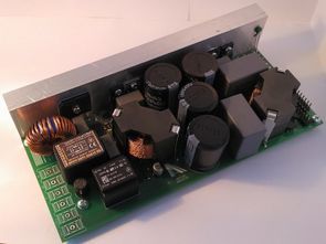
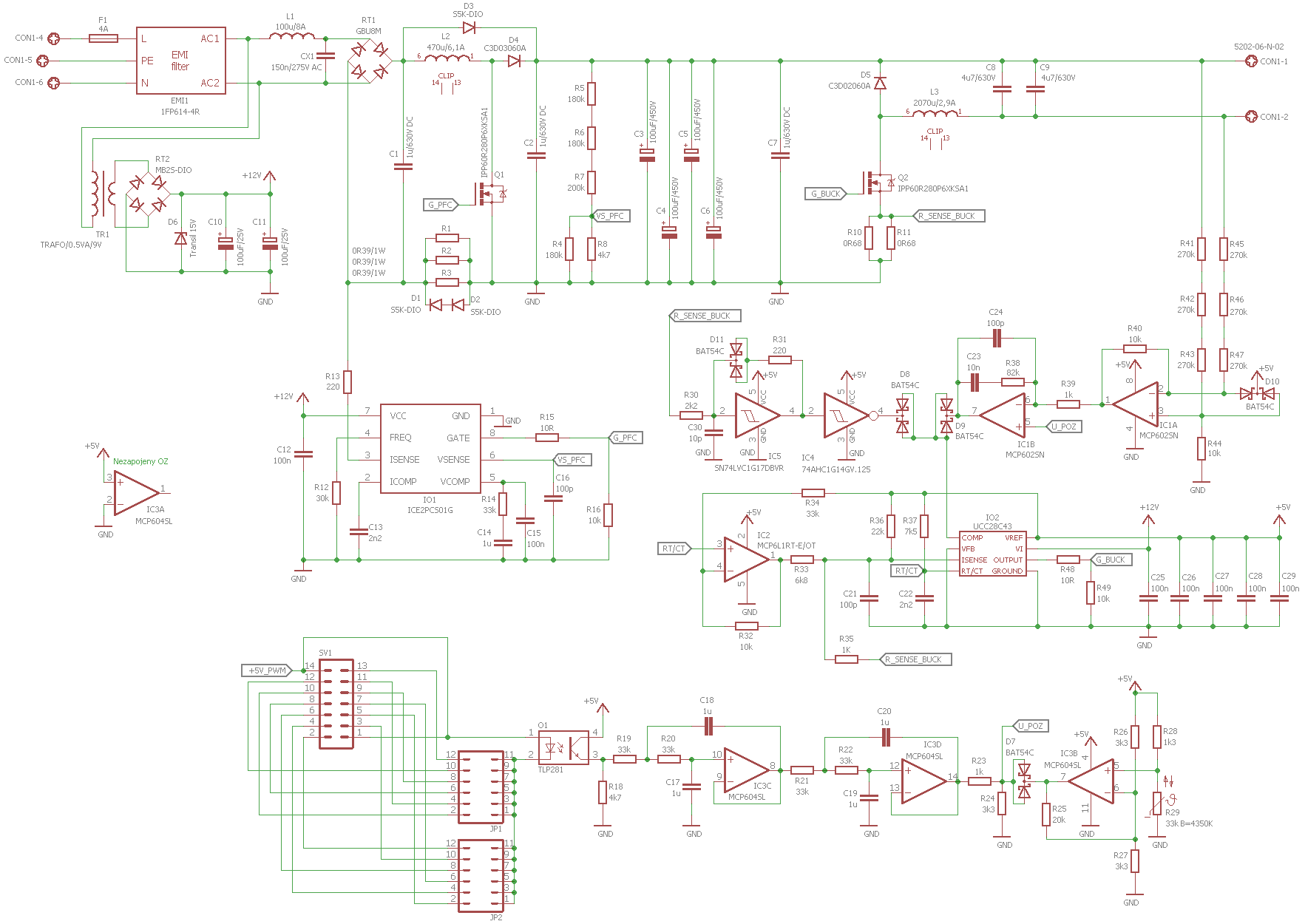
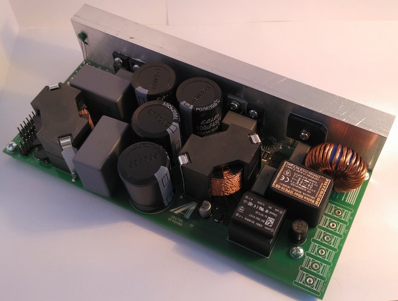
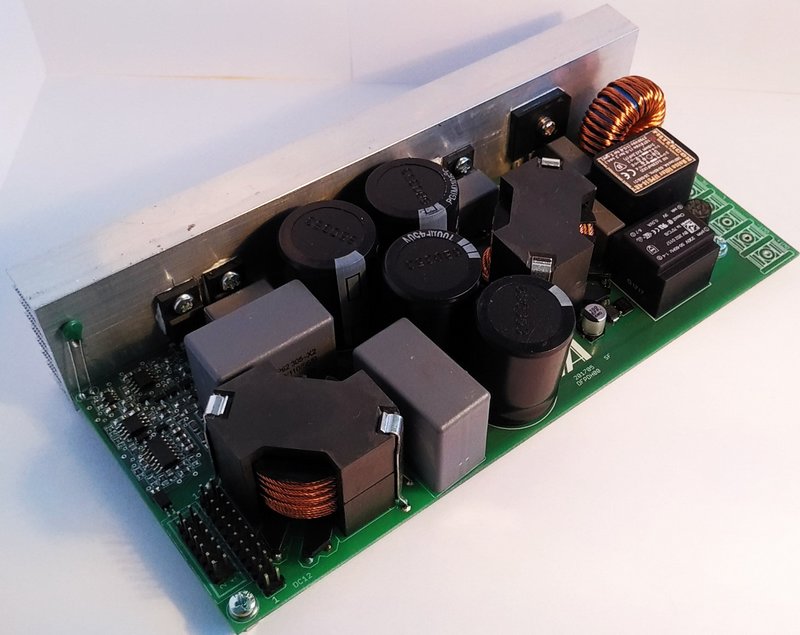
600W LED Dimmer Circuit Schemetic
![]()
FILE DOWNLOAD LINK LIST (in TXT format): LINKS-26196.zip


CDI Circuit TL494 PC power transformer EI33
CDI Circuit TL494 PC power transformer EI33
The reproducibility of DC-CDI in most implementers faces the difficulty and little experience of transformer winding. Therefore, this design, based on DC-CDI is used to transform the voltage using a PC power transformer EI-33. So there is no need to wind up any transformer.
The necessary EI-33 transformer can be obtained from older types of PCs. The easiest to know is that the source contains (most often) a common, independently guided GND transformer output (braided wires see photo). And most often as a control integrated circuit is used TL494 or some of its Asian clone (KA7500, KIA494 etc.)
The EI-33 transformer usually contains two symmetrical secondary windings for 12V and 5V distributions with a common center of both windings. Thus, the direction of transformation can be rotated in a simple way. Transformers are always wound up for 120V (and 230V) wiring, so we only get 150V when rotating the transformer, which is very little for proper CDI operation. Thus, the output portion contains a voltage doubler D1, D2, C1 and C5, as opposed to the conventional CDI version. Discharging capacities (spark ignition spark plug) is provided by IGBT transistor Q1. The input section contains a pair of insulating optocouplers that provide galvanic isolation of the input of the inverter from the excitation part of the ignition (eg hammer, hall, optocoupler) and with the control LED1 it forms one unit in series. LED1 is wired to optically check the optron functionality.
Circuit de gradateur LED 600 W PFC ICE2PCS01 UCC28C43
Ce bloc est utilisé pour réduire et stabiliser la tension produite par le bloc PFC. La tension de sortie de ce bloc est contrôlée par le signal de commande. La tension de sortie étant supérieure à la touche de sécurité (selon la norme CSN), il est possible d’utiliser l’interrupteur inférieur sur l’entraînement d’abaissement. Le circuit intégré UCC28C43 est utilisé pour le contrôle
Tout d’abord, une partie du PFC a été installée pour faciliter la localisation des défauts. Les composants périphériques de ce bloc ont été installés et exécutés à travers une ampoule connectée en série qui sert de protection contre un éventuel court-circuit. La figure (Fig. 3.3) contient l’oscillogramme avec la tension de commande et la tension sur le transistor Q1 sans charger la sortie PFC. La charge sur la charge PFC a été progressivement connectée à la sortie dont la perte de puissance 140, 330, 500 et 660 W a été générée. contiennent un oscilloscope avec des formes d’onde de tension PFC à 660 W et une tension d’entrée de 220 V. La forme d’onde du courant d’entrée est approximativement sinusoïdale. La tension moyenne de la sortie PFC est de 370 V. L’ondulation de tension est de 16 volts.