Led cube pic16f688 microcontroller used in the output driver circuit in the CA4016 LED (adjustable driver 16 channel flow ) is being integrated over. Prepared with PIC16F688 assembly source software. Asm, pcb printed circuit diagram hex codes list of materials have everything complete project
5x5x5 LED Cube pictures and videos of the drive circuit;
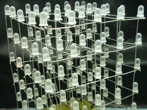
LED cube is made up from 125 LEDs arranged into 5 layers of 25 LEDs each. The display itself is multiplexed so instead of requiring 125 connections it requires one to each of the five layers and 25 to each LED in a layer making a total of 30. The cube is refreshed by a software interrupt routine with each layer active for 2ms, so the entire cube is refreshed every 10mS (100Hz). This results in a display with no visible flicker. LED cubes, small 3x3x3 cubes, bi-colour, RGB and mono cubes, amazing 16 x 16 x 16 RGB cubes. However, very few show you how to make one and provide the firmware. 5x5x5 LED cube project shown here is a great size if you want to have ago at building a LED cube. Why? because it gives a good balance between the number of LEDs and therefore cost and time needed to assemble it and the overall 3-D effect. 8x8x8 or even 10x10x10 cubes look good and it doesn’t sound much more work than a 5x5x5 cube but you’re going from 125 LEDs to 512 or 1,000 LEDs in a 10x10x10 cube – that’s alot of work.

Source: picprojects.org.uk/projects/lc/index.htm
FILE DOWNLOAD LINK LIST (in TXT format): LINKS-18134.zip


Thermometer Circuit LM35 PIC12F675
LM35DZ circuit is used as temperature sensors. This sensor is able to output between 0 and 100. The reason for choosing the microcontroller 12F675 and 12F675 jalv2 languages in use in the show as well as the insufficient number of pins used with a controller is to demonstrate how the display.
When the circuit actually be done, within the red frame on the right side resistance 3, simulation studies used to ensure a more healthy because it will be used.