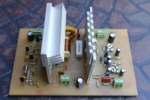
The 40-meter AM transmitter circuit with IRFP150 MOSFET is a project with approximately 5W carrier output, consisting of a 7MHz crystal oscillator, discrete-transistor RF driver, drain-modulated power stage, and electret microphone preamplifier. It offers a structure with clear adjustment points and high component availability for radio amateurs who want to perform local AM communication experiments.
Operating Principle of the Circuit
Contents
- 1 Operating Principle of the Circuit
- 2 Main Blocks in the Circuit
- 3 Output Filter and Antenna Connection
- 4 Coil and RF Choke Coil Notes
- 5 Functions of Important Components
- 6 Technical Summary
- 7 Adjustment Points
- 8 Highlights in the Component List
- 9 Points to Consider During Setup
- 10 First Startup Sequence
- 11 Common Mistakes
- 12 Legal and RF Safety Warnings
40-meter 5W AM transmitter circuit schematic with IRFP150 MOSFET
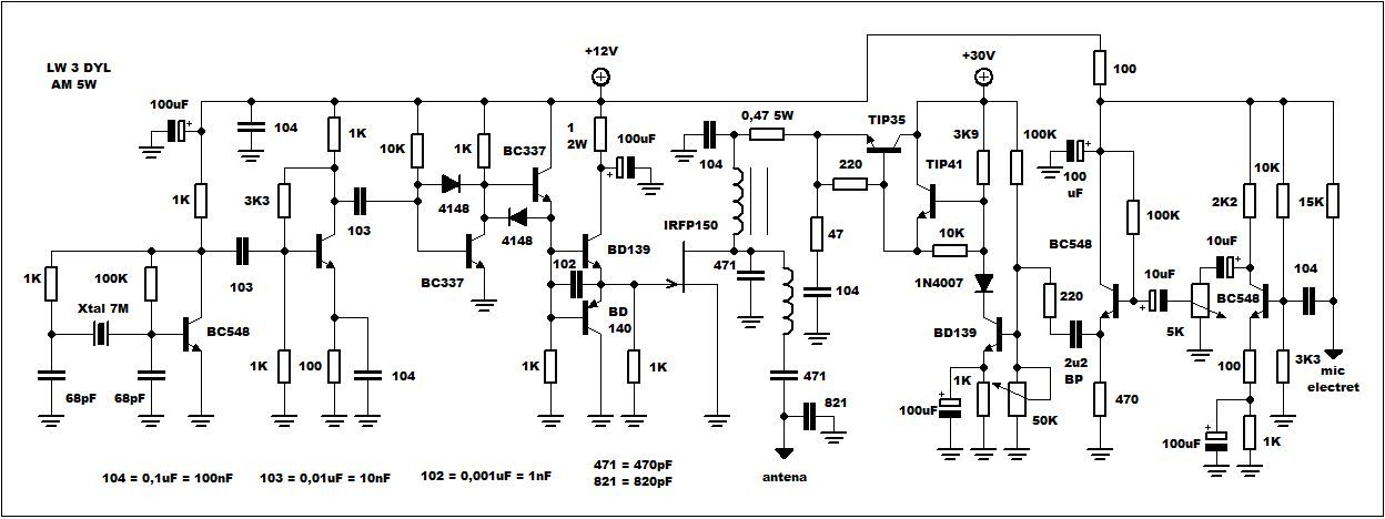
When the circuit is read from left to right, four main sections are seen: 7MHz crystal oscillator, RF amplifier and driver stage, IRFP150 MOSFET power stage, and AM modulator section with electret microphone.
The RF side operates with +12V; the drain supply of the power stage comes from the +30V line through the modulator.
The schematic states that it can also operate with +24V, but the adjustment voltages must be rearranged accordingly.
AM generation is based directly on changing the amplitude of the RF signal. The crystal oscillator generates a carrier at a fixed frequency, the IRFP150 amplifies this carrier, and the audio signal modulates the carrier amplitude by changing the drain supply of the MOSFET.
Therefore, although the audio stage and RF power stage appear independent from each other, the AM quality at the transmitter output depends on both being adjusted correctly together.
Main Blocks in the Circuit
7MHz Crystal Oscillator
The BC548 transistor on the left side generates a stable RF carrier with the 7MHz crystal.
Using a crystal prevents the frequency from depending on mechanical coil adjustment. In the schematic, the oscillator section built with 68pF capacitors and 100K resistors has a sufficiently simple structure for fixed-frequency AM experiments in the 40-meter band.
If the crystal frequency will be changed, the band plan and legal operating range must definitely be checked.
Crystals such as 7,150MHz, 7,164MHz, or 7,200MHz can be found; however, it should not be assumed that the same frequencies are suitable for the same mode in every country.
RF Amplifier and Shaping Stage
The low-level RF signal coming from the oscillator is transferred through 103-coded coupling capacitors to the intermediate stages with BC548 and BC337 transistors.
The purpose here is not only to increase the amplitude; it is also to prepare a more stable and sufficient-level signal for the IRFP150 gate driver.
The 1N4148 diodes act as clipping elements that limit the signal level and prevent the driver stage from being overstressed.
If this section remains weak, the IRFP150 cannot be driven fully; if it is overdriven, the spectrum deteriorates and unwanted harmonics may increase despite the output filter.
BD139 / BD140 Totem Pole Driver
The BD139 and BD140 pair is used to drive the gate terminal of the IRFP150 MOSFET with lower impedance.
Although the gate terminal of power MOSFETs appears not to draw DC current, the gate capacitance becomes a serious load at high frequency.
If a weak transistor stage cannot charge and discharge the gate quickly, the MOSFET spends too much time in the switching region and heats up unnecessarily.
It is important to keep the connections short in this section. A long cable or thin PCB trace on the gate line creates a suitable environment for RF feedback and unstable operation.
IRFP150 RF Power Stage
The IRFP150 is the main component that produces the RF output power of the circuit. Its source terminal is connected to chassis; its drain terminal both receives energy from the modulated supply line and transfers RF to the output LC network.
The IRFP150 is not a transistor specially manufactured for RF, so correct driving, short connections, good cooling, and output matching are mandatory.
The schematic particularly draws attention to adding a 470pF 500V capacitor between the drain and source of the IRFP150 with a very short connection.
This capacitor should be soldered on the copper side of the PCB, close to the MOSFET legs. If it is installed with long leads, it will not show the same effect; it may even create additional parasitic inductance at RF.
AM Section with MOSFET Drain Modulation
The electret microphone preamplifier on the right side is built with BC548 transistors.
After the microphone signal passes through several coupling capacitors and gain adjustment, it reaches the modulator stage around BD139, TIP41C, and TIP35C.
This stage creates AM modulation by changing the IRFP150 drain supply according to the audio signal.
The 5K preset is used to adjust the modulation level. If it is opened too much, clipping at the carrier peaks and overmodulation occur.
The 50K preset determines the drain operating voltage of the power stage. When a +30V modulator supply is used, the drain voltage should be adjusted to approximately 18V.
When operated with a +24V supply, the same ratio corresponds to approximately 14V to 15V.
Output Filter and Antenna Connection
The RF energy coming from the IRFP150 drain terminal is transferred to the antenna through an output network consisting of a coil and high-voltage capacitors.
The 471 code in the schematic means 470pF, and the 821 code means 820pF. Choosing these capacitors as 500V is not accidental; the peak voltages seen at the RF output can be much higher than the supply voltage.
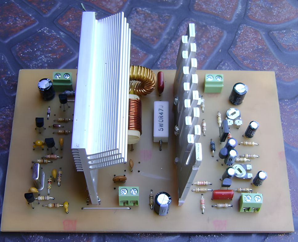
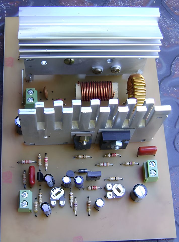
The output coil is wound with approximately 18 turns on a 10mm diameter form. 0,70mm or 0,80mm enameled copper wire is suitable as the wire.
The coil spacing, actual values of the capacitors, and parasitic capacitances on the PCB directly affect the output power.
Therefore, the first adjustment must definitely be performed on a 50 ohm dummy load.
Coil and RF Choke Coil Notes
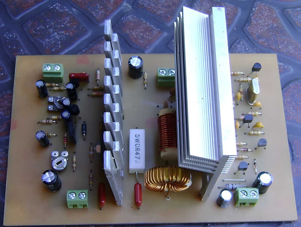
The RF choke coil on the drain supply line prevents RF from leaking into the +30V modulator line.
In the original structure, many turns were wound on a yellow PC power supply toroid.
The function of this coil is to create high impedance for RF and low resistance for DC.
The output coil works for filtering and impedance matching. The two coils do not do the same job; one separates the supply line from RF, while the other determines the adjustment of the signal transferred to the antenna.
If the number of turns or diameter of the output coil changes, the resonance point obtained with the 470pF and 820pF capacitors also changes.
Functions of Important Components
| Component | Function in the circuit | Point to note |
|---|---|---|
| 7MHz crystal | Determines the carrier frequency. | The frequency to be used should be selected according to the amateur band plan. |
| BC548 | Used in the oscillator and microphone preamplifier stages. | The pinout should be checked according to the manufacturer. |
| BC337 | Used in the RF intermediate stage and signal shaping section. | Short connections and solid grounding are important. |
| BD139 / BD140 | Forms the totem pole stage that drives the IRFP150 gate terminal. | Heating should be checked and connections should be kept short. |
| IRFP150 | It is the MOSFET that produces the RF power output. | Good heatsink, insulation, and correct output adjustment are required. |
| TIP41C / TIP35C | Operates in the AM modulator and drain supply control section. | It should be mounted on the heatsink with electrical insulation. |
| 1N4148 | Performs signal limiting in the RF driver section. | Reverse orientation or incorrect connection distorts the drive level. |
| 1N4007 | Undertakes protection and steering functions in the modulator section. | It should be connected in the direction shown in the schematic. |
Technical Summary
| Feature | Value / Description |
|---|---|
| Operating band | 40-meter amateur band, around 7MHz |
| Modulation type | AM, drain modulation |
| RF power component | IRFP150 MOSFET |
| RF supply | +12V oscillator and driver stage |
| Modulator supply | +30V recommended, can also operate with +24V |
| Expected carrier power | Approximately 5W |
| Approximate current consumption | 500mA – 600mA range |
| Drain adjustment | Approximately 60% of the modulator supply |
| Output adjustment | Should be performed with a 50 ohm dummy load |
| PCB size | Approximately 10 x 15cm |
Adjustment Points
MOSFET Drain Voltage Adjustment
The 50K preset determines the carrier operating point of the IRFP150 drain line. With a +30V supply, the drain voltage is adjusted to approximately 18V. This adjustment is important not only for output power, but also for modulation symmetry.
If the drain voltage remains too low, the output power decreases; if it is increased too much, clipping at the modulation peaks and MOSFET heating increase.
Modulation Level Adjustment
The 5K preset controls the microphone level and modulation depth. During adjustment, focusing only on making the sound louder is wrong.
Overmodulation causes sideband splatter and distorted sound in the AM signal. The safest adjustment is made at the point where the carrier envelope is not distorted, using an oscilloscope or SDR spectrum display.
Output LC Adjustment
The output filter is the most critical section that transfers RF power to the antenna. An antenna should not be used in the first test. A 50 ohm dummy load, RF wattmeter, and current-limited supply should be used at the beginning.
If the drain current rises abnormally while the output power increases, there may be a mismatch in the coil or capacitor values.
Highlights in the Component List
40-meter 5W AM transmitter circuit component list

| Group | Components | Note |
|---|---|---|
| Semiconductors | IRFP150, BD139, BD140, BC548, BC337, TIP41C, TIP35C, 1N4148, 1N4007 | Transistor pinouts should be checked for different manufacturers. |
| RF capacitors | 68pF, 470pF 500V, 820pF 500V | Low-loss types with suitable voltage ratings should be preferred on the output side. |
| Coupling and bypass capacitors | 1nF, 10nF, 100nF, 2,2uF BP, 10uF, 100uF, 470uF | 104 = 100nF, 103 = 10nF, 102 = 1nF. |
| Resistors | 0,47 ohm 5W, 1 ohm, 47 ohm, 100 ohm, 220 ohm, 470 ohm, 1K, 2K2, 3K3, 3K9, 10K, 15K, 100K | Power resistors and low-value resistors should be checked in terms of heating. |
| Adjustment components | 5K preset, 50K preset | One adjusts the modulation level, and the other adjusts the drain operating voltage. |
| Mechanical parts | 10 x 15cm board, 7cm heatsinks, terminal blocks | Insulating washers should be used on the IRFP150 and modulator transistors. |
Points to Consider During Setup
- When the IRFP150, TIP35C, and TIP41C are mounted on the heatsink, they should be electrically insulated with mica or sil-pad.
- The RF output capacitors should not be replaced with low-voltage ceramic types.
- The 470pF 500V capacitor between the IRFP150 drain-source should be installed on the copper side and very close to the legs.
- The gate driver line should not be routed with a long cable.
- The oscillator and microphone preamplifier supply line should be well bypassed.
- A 50 ohm dummy load must definitely be connected to the output during the first startup.
- The power supply should be current-limited, or series protection should be used during the first test.
First Startup Sequence
- After soldering is complete, check for a short circuit between the +12V and +30V lines.
- Verify with an ohmmeter that the IRFP150 gate, drain, and source terminals go to the correct points.
- Connect a 50 ohm dummy load to the output instead of an antenna.
- First apply the +12V line and check that the oscillator and driver section are operating.
- Apply the +30V modulator line in a current-limited way.
- Adjust the drain voltage to approximately 60% of the supply voltage with the 50K preset.
- While increasing the microphone level with the 5K preset, check that overmodulation does not occur.
- Output power, drain current, and MOSFET temperature should be monitored at the same time.
Common Mistakes
| Mistake | Result |
|---|---|
| Connecting to the antenna without adjusting the output filter | High SWR, low power, and IRFP150 failure may occur. |
| Opening the modulation preset too much | Overmodulation, distorted sound, and out-of-band splatter are observed. |
| Adjusting the drain voltage too close to the supply voltage | The AM envelope does not form properly, and the power stage is stressed unnecessarily. |
| Connecting the 470pF capacitor on the IRFP150 with long leads | The oscillation suppression effect decreases. |
| Not using insulation on the heatsink | A short circuit may occur through the transistor bodies. |
| Transmitting without checking the crystal frequency | Operation may occur on the wrong frequency or in an unsuitable part of the band. |
Legal and RF Safety Warnings
A transmitter operating around 7MHz should only be used by radio amateurs with the appropriate authorization and on permitted frequencies.
The circuit should not be considered low-power during testing; a 5W carrier AM signal can cause unwanted interference in the surrounding area through a poorly adjusted antenna or harmonics.
During long-term tests, the dummy load heats up. If the power rating of the load resistor is not sufficient, the resistance value changes and the adjustment becomes misleading.
The RF output line should not be touched by hand while operating, and an insulated tool should be used for adjustment.
Source: qrplw3dyl.blogspot.com/2024/12/transmisor-de-am-5w-40m.html