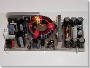
SMPS circuit SG3525 and IR2110 integrated on the board in the primer drive MOSFETs IRPF450 transformer, the ETD44 feedback 4N33 opto-Kubla with the provided output voltage of 2 × 60 volts symmetrical about 450w has the power amp ideal for feeding additional output TIP31 and TIP32 transistors with + – 12 volt regulated There are tons of solid control, etc. preanf. To run as an additional power supply circuits do not need to use.
Simple transformerless power supply circuit for outside sources;


Circuit diagram and PCB drawing has a simple design of all parts can be found on the market in the testing phase 220v and output filters of emi use of coils in the PC power supply is not critical parts can make a robust system according to the situation 🙂

In the circuit diagram portions separated this way, the system easier you realize, for example TIP50 made with 13v regulator circuit this circuit high voltage (primary) section + output connected to the SG3525 SMPS control integrated nourishes rather first study providing start after giving ETD44 wound on a 3-lap winding the whether regulated by the control section 7812 dvr 24v SG3525 continues to feed.
SMPS Startup Circuit

This method is used in the design of a very SMPS circuit can be regulated as transistor or integrated as uc384x series we have seen in the first study of high-value resistor is customary to start one. But remember, these systems are not strong enough to nourish integrated so as I explained above, additional supply must supply additional windings or .3 watts 2 times the normal control can be supplied with a transformer. SMPS circuit circuit used in combination Fortunately, we have ascertained the start 🙂
CAUTION Be careful is working with high voltage capacitor circuit connections Beware + – If you connect the high voltage polarity may be large explosions before running the insured circuit power line, use protective glasses
SG3525 IR2110 60v switch mode power supply schema pcb files alternative link:


300W Amplifier Circuit
Rms 300w amplifier circuit quite strong bipolar transistors based on the output mj15025 and mj15024 transistor-used according to the power supply voltage high + – 82 volts DC total 164v dangerous value test and run stages Be careful fused electrical lines, protective goggles.
Bipolar Transistor 300W Amplifier