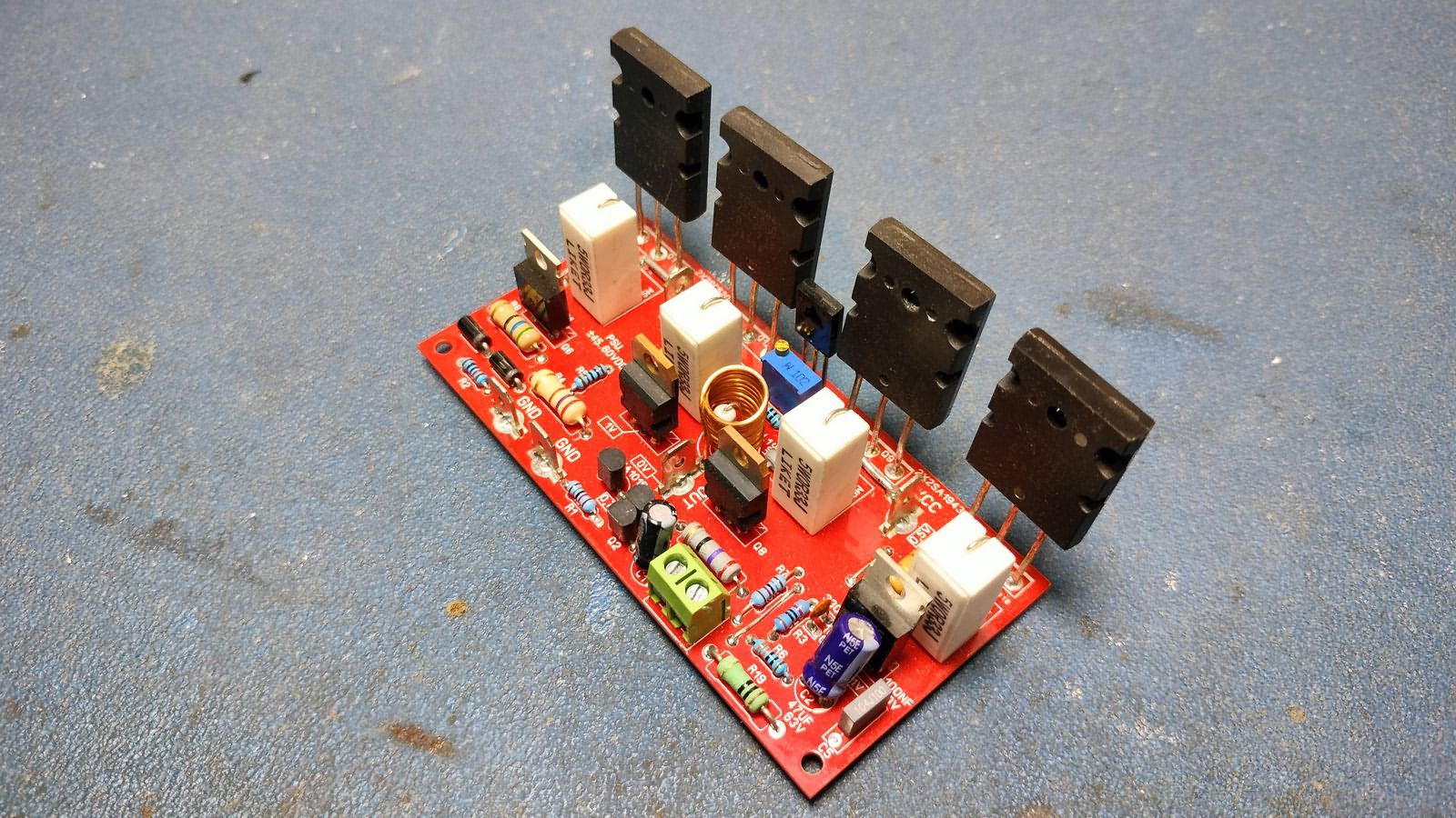
200W Amplifier Circuit 2SC5200 2SA1943 (New PCB) The 200 Watt amplifier circuit I shared in the article has the quiescent current regulation done. Transistor, trimpot and resistor were added. PCB design was edited.
The information I gave in the previous article is valid, I am just summarizing.. I would like to state that the sound quality of this amplifier circuit is really a quality design that I have not seen in other transistor amplifiers I have applied…
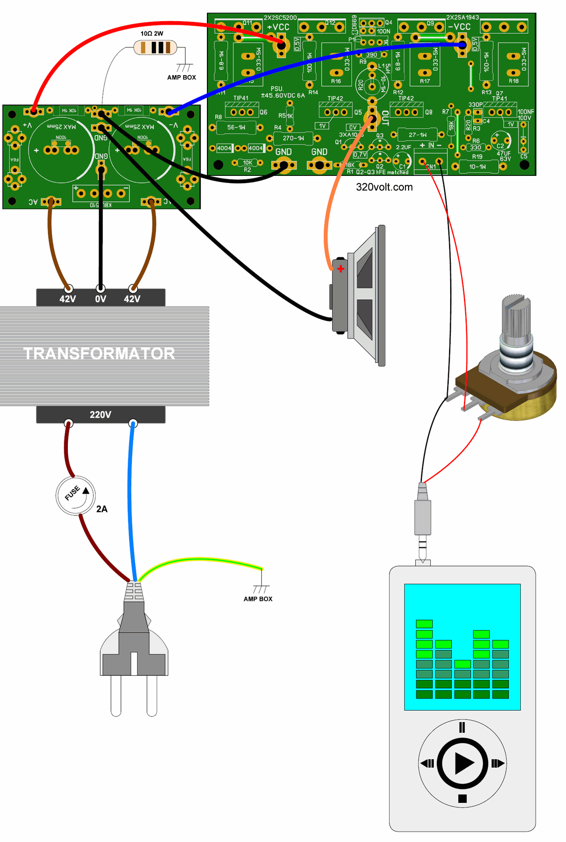
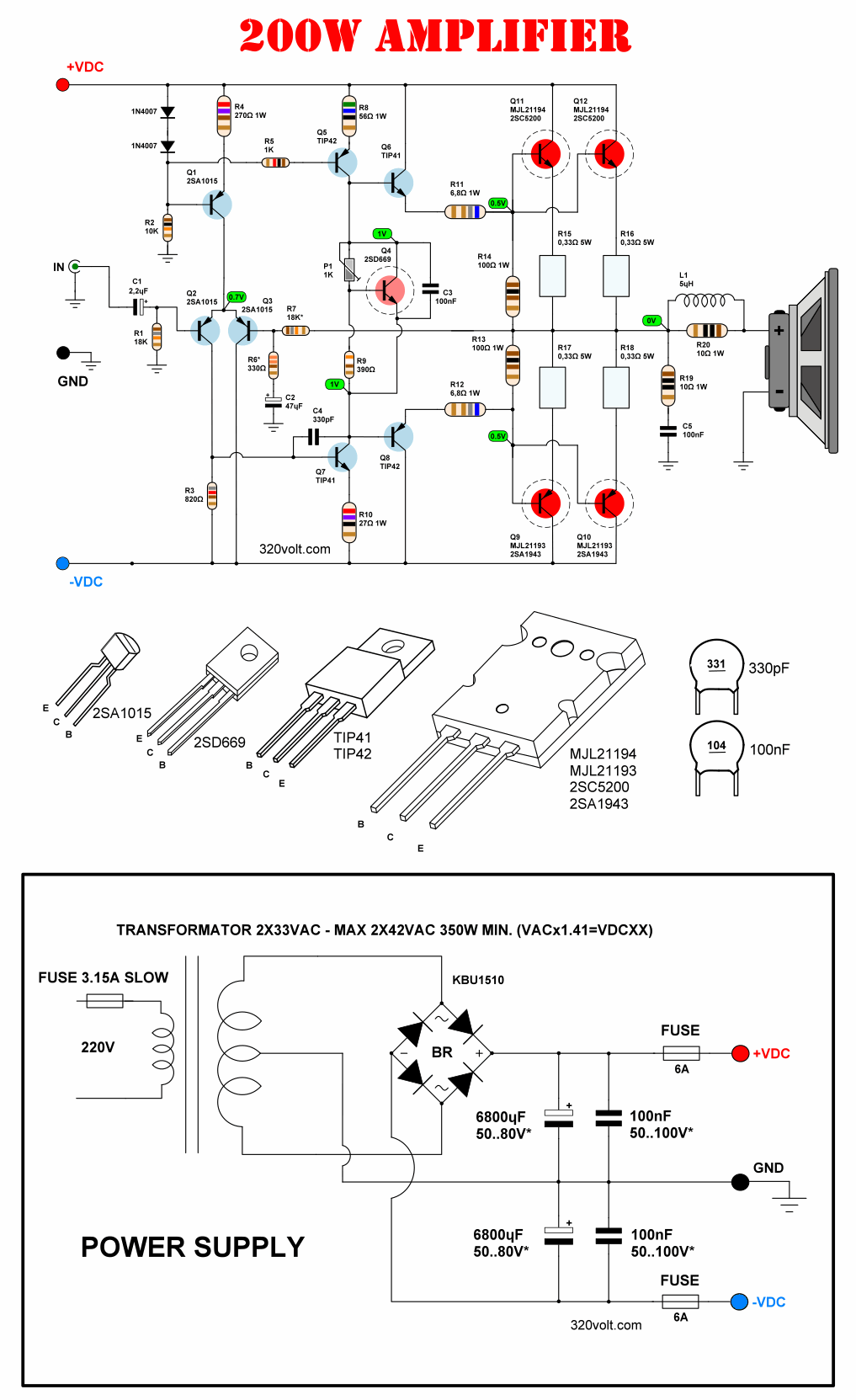
Output Power: 200W RMS with 4Ω speaker 100W RMS with 8Ω speaker
Operating Voltage: ±45V…60V DC (2x33VAC or 2x42VAC transformer is suitable)
DC Filter Capacitors: 4700μF – 10,000μF is recommended.
Bridge Diode: KBU10M or 4x P600J (6A) can be used.
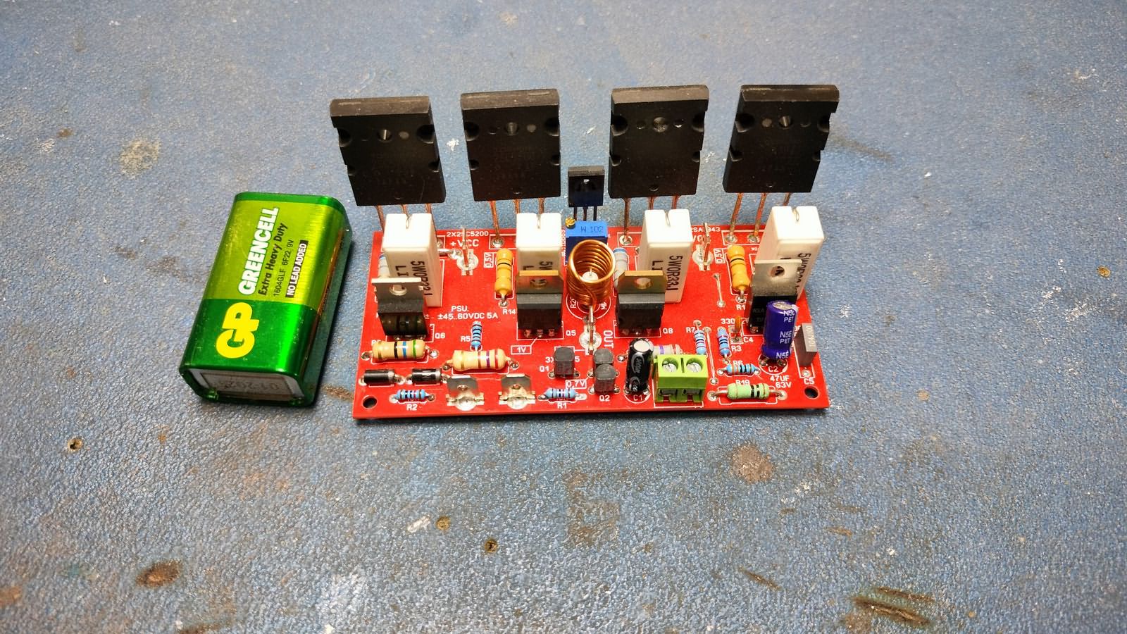
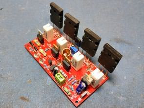
200W Amplifier
2SA1015 Be careful with the audio input and other transistors. There are many fake transistors on the market. The hFE value should be measured for authenticity (should be about 180). Alternative: 2N5401 (the pin connections are different, be careful when assembling!).
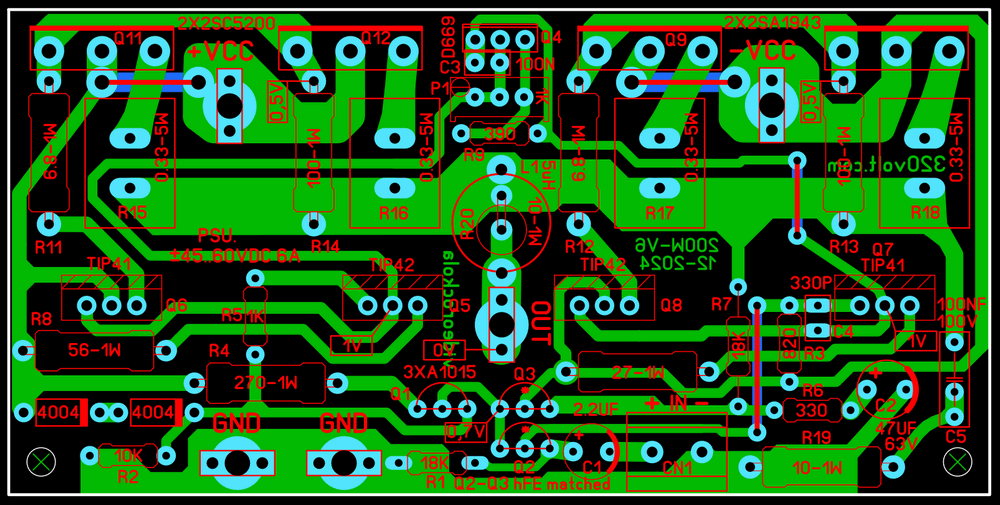
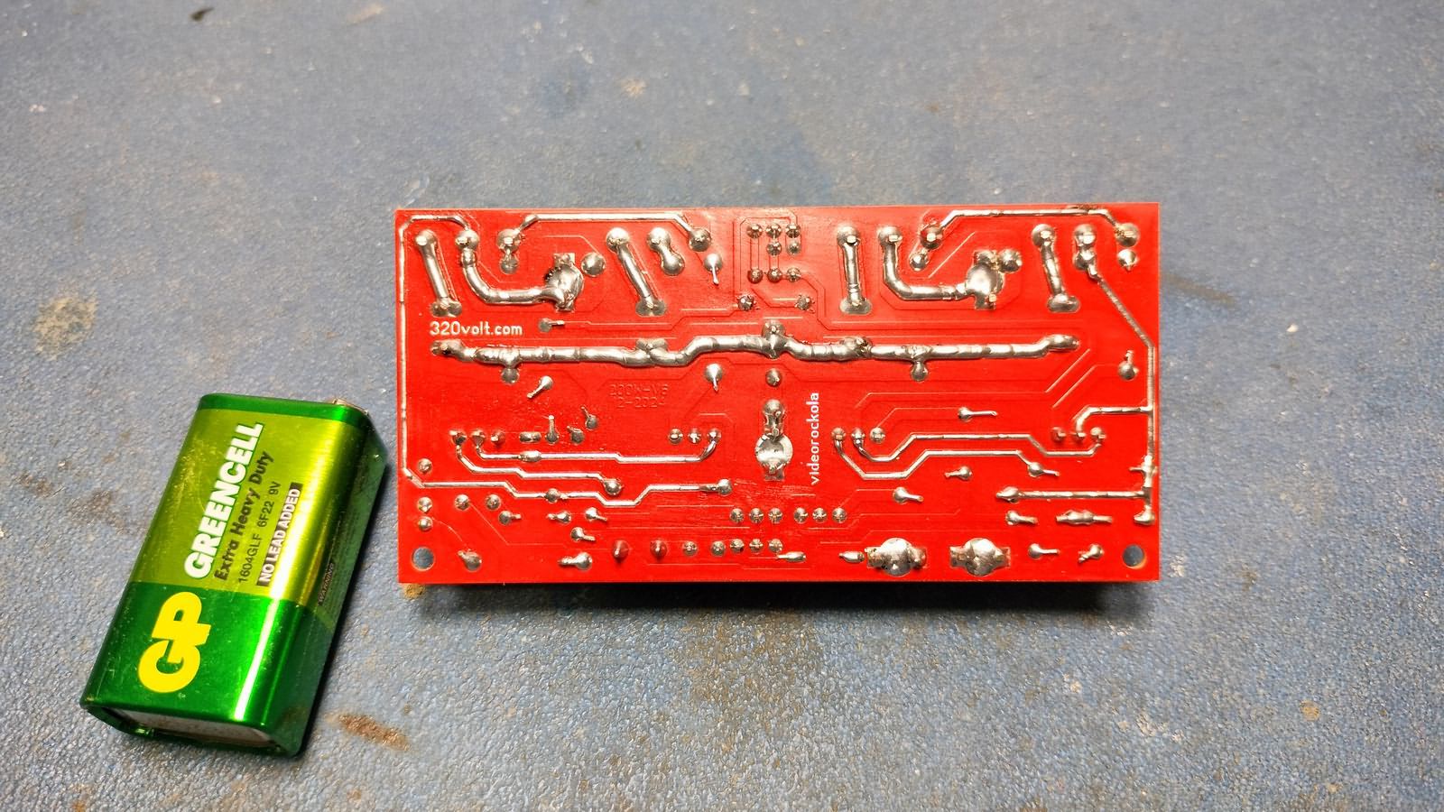
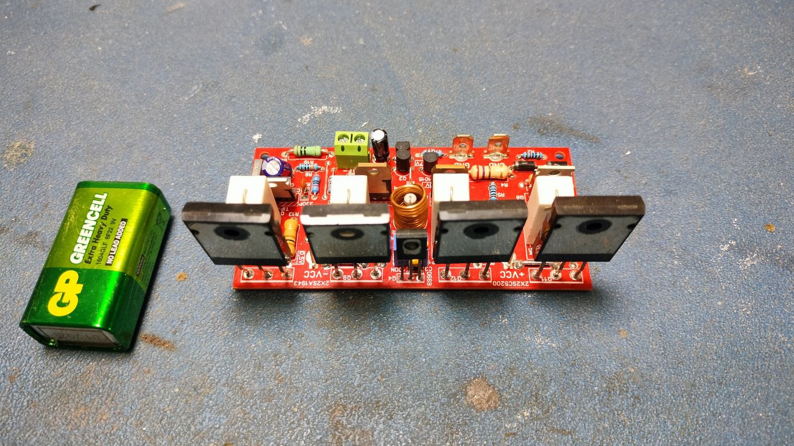
5μH Coil: 11 turns with 1mm wire (58mm diameter drill bit can be used). PCB Dimensions 100x49mm (single layer, designed with Sprint Layout 6 ).
200 Watt Amplifier Wiring Diagram