2SA1943 2SC5200 200W Amplifier Circuit

| August 20, 2023 Updated
2SA1943 2SC5200  200W Amplifier Circuit

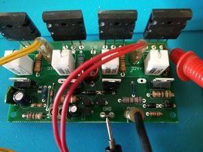
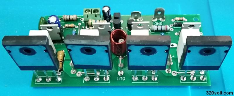
The single channel 200W version of the amplifier shared in the article 400w (2X200w) Transistor Amplifier Circuit was designed as small as possible in PCB size.

The power transistors of the 200W Afi circuit do not require the classic 2SC5200 and 2SA1943 quiescent current adjustment. The amplifier can deliver 100W RMS power with a 4-OHM speaker and a 200W RMS 8-OHM speaker.

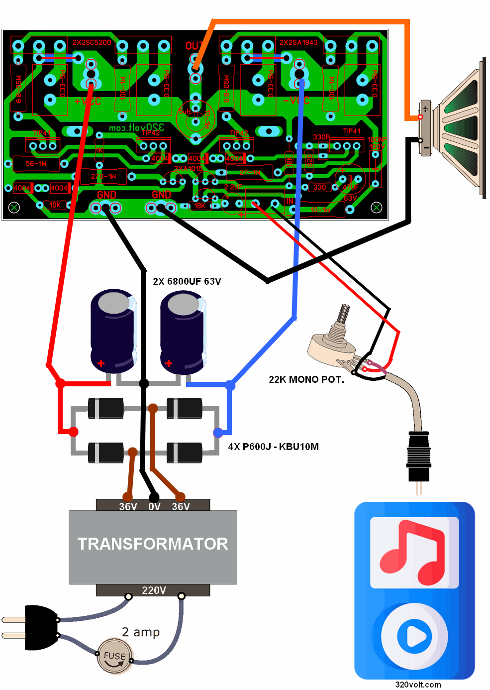
Amplifier operating voltage max. 2X50V DC 6A (2X33VAC or 2X36VAC transformers can be used) supply filter capacitors For usable bridge diodes between 4700uf… 10.000uf, ready KBU10M or 4 P600J 6 ampere diodes can be used.

330PF capacitor protects the amplifier from high frequency oscillations. If you cannot find a 330PF, you can use a 270PF capacitor instead.

The author says about the 2SA1015 transistors that counterfeits are a lot on the market. To understand that the transistors are original, it is necessary to measure BETA or hFE with a digital multimeter. The 2SA1015 should show 180 or slightly less in the hFE measurement. 2N5401 can be used instead of 2SA1015, but the leg connections are different, be careful with this, the basin and collector legs should be changed in the PCB assembly (I have experimented with the 2SA733 transistors I have)

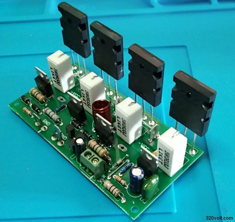
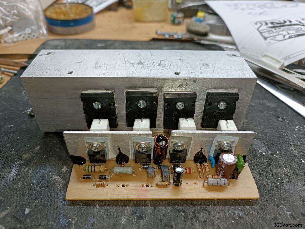
2SC5200 and 2SA1943 transistors need to use insulators in the cooler assembly.You can look at the article Heat conduction and insulators for details, the equalization resistors of output transistors 0.33-OHM….

The author said that a cooler can be used for TIP41-TIP42 transistors, but I left a hole for the cooler installation, but you can install 2 pieces of 2mm aluminum strip or a separate small cooler for all of them or you can look at the heat condition.

The 5uH coil must be wide enough to pass into a 10-OHM 1W resistor to be wound 11 rounds of 1mm wire. I used a drill bit.

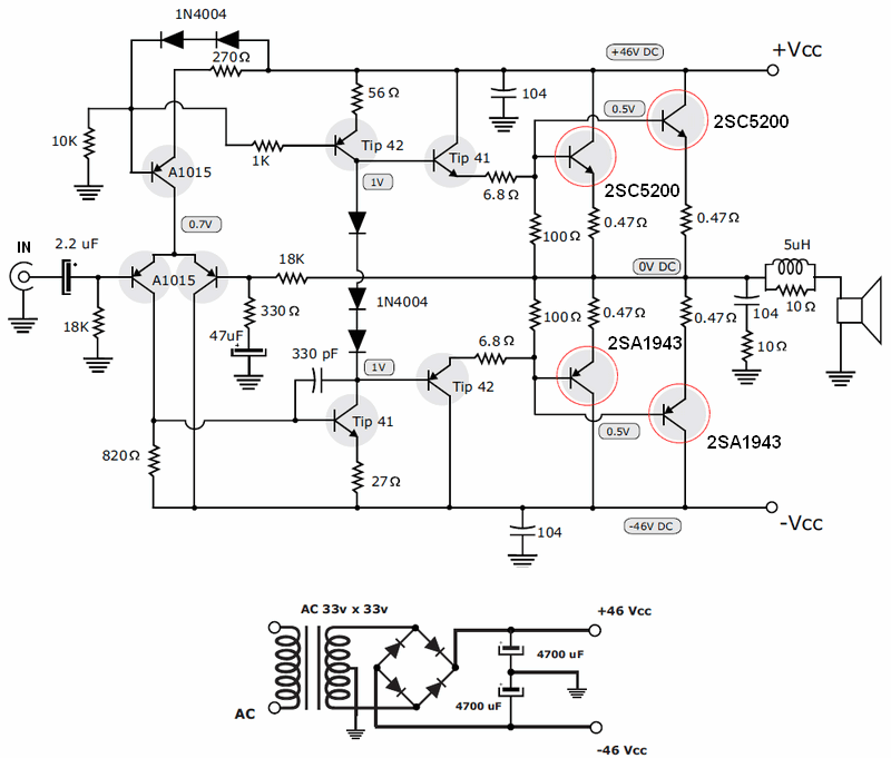
200W Transistor Amplifier Circuit Diagram

200w-transistor-amplifier-circuit-diagram

200w-amp-pcb-sprint-layout

200W Amplifier Test and Voltage Measurements


The source of the circuit is reliable, and since the circuit was made by our readers before, I made the assembly of the materials and went directly to the test.I had a 2X30V transformer and 50W bass and 30W normal speaker cabinet.I could not raise the volume much more than 50% sound quality, power was very good 27-OHM 1W resistor I did not have. instead I used 2 pieces of 56-OHM connected in parallel.

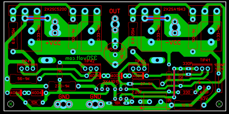
Printed circuit PCB dimensions are 100X49mm and single layer PCB drawing was made with Sprint Layout PCB program.

I used C1 in the upper layer to strengthen the voltage inputs and outputs. If you are going to print PCB at home, do not select C1 when printing.

project-hi-fi-amplifier-circuit-200w-pcb-board-diy-2sc5200-2sa1943

diy-project-hi-fi-amplifier-circuit-200w-pcb-board-diy-2sc5200-2sa1943

Note: I added the SMD option for 330PF in PCB Design, but removed it from the drawing to avoid confusion. The 18K SMD resistor in the audio input has been changed to be DIP casing assembly.Finally, I removed the optional SMD filter capacitors, they were already staying away from the supply inputs, and the voltage input lines are very short and the roads are thick.

Finally, when 2SC5200 and 2SA1943 are used for the writer output transistors (2SD1047 (NPN) 2SB817 (PNP)), the max. He says that it can be 2X62V DC, in this case the voltage of the capacitors used must be above 63V and instead of TIP41 TIP42 2SCC2073 (NPN) 2SA940 (PNP) or 2SA1837 (PNP) 2SC4793 (NPN) should be used. I think 2X50V is enough, even if you say I don’t want loud sound, it could be 2X30V

200W Amplifier Power supply and audio connection

200w-amplifier-connection-power-audio

200W Amplifier Component List

Transistors

2X 2SC5200
2X 2SA1943
3X A1015
2X TIP41C
2X TIP42C

Resistors

2X 6.8-OHM resistor – 1W (blue, gray, gold)
2X 100-OHM- 1W (brown, black, brown)
2X 10-OHM – 1W (brown, black, black)
270-OHM 1W (red, purple, brown)
56-OHM 1W (Green, blue, black)
27-OHM 1W (red, purple, black)
4X 0.47-OHM 5W or 0.33-OHM 5W stone resistor
820-OHM 1 / 4W (gray, red, brown)
10K – 1 / 4W resistor (brown, black, orange)
330-OHM 1 / 4W (orange, orange, brown)
18K – 1 / 4W (brown, gray, orange)
1K – 1 / 4W (brown, black, red)

Capacitors

100NF (104) 100v
47uF 63v
2.2uF 63V
330pF (331) (ceramic or multilayer)

Diodes

5X 1N4004

Thanks for the feedback @sina

iran-arabia-2sa1943-2sc5200-200w

FILE DOWNLOAD LINK LIST (in TXT format): LINKS-27565a.zip

source: videorockola.com

Published: 2021/01/12 Tags: ,


18 Comments “2SA1943 2SC5200 200W Amplifier Circuit

  1. Christophe quadrosChristophe quadros

    HI
    can i use 60 v +/- DC for this amplifier

    REPLY
    1. gevvgevv Contributor

      Hi, yes available

      Author note (source site);

      The Transformer that we use in the prototype that we show in the video has a voltage of 33-0-33 volts AC. It means that when measuring from end to end, we have 66 volts AC, and when measuring from each end to the central TAP, we get 33V AC. With this voltage, the amplifier gives us a total power of 300W.

      If we want to get the real 400W (200W per channel) from the amplifier, we must use a 40-0-40 volt AC transformer.

      The reason we did the project with a lower voltage transformer was for people who don’t have enough money for a big transformer. Thus we would have an economical version and also a more expensive one, which provides better performance.

      In case you get a very high voltage transformer, more than 45+45V AC and you want to condition it, you can remove a few turns of wire, until you get the right voltage for this amplifier. An even better option is to build another amp that uses more voltage, like our 500W Stereo Amplifier, which uses a 55+55V transformer.

      The ideal current to achieve a good performance of this amplifier is 12 amps. Remember that this also depends on the transistors you use at the output. In case of using 2SC5200 and 2SA1943 transistors, they need a minimum current of 1 amp, therefore we recommend using a transformer of at least 8 or 10 amps.

      REPLY
  2. ManuelManuel

    hola buenas, esta super el circuito te estoy muy agradecido por tu gran aporte, mira me quiero hacer un amplificador de guitarra, me puedes orientar? si deseo instalar un pre-amplificador a tubo como puedo bajar la impedancia entre el tubo y la entrada del circuito de 200watts? con un buffer?

    REPLY
    1. ManuelManuel

      hello good, the circuit is super I am very grateful for your great contribution, look I want to make a guitar amplifier, can you guide me? If I want to install a tube pre-amplifier, how can I lower the impedance between the tube and the circuit input of 200 watts? with a buffer?

      REPLY
  3. sinasina

    Hello
    Thanks for this circuit
    My question is, is there any problem with this part of the circuit?
    Shouldn’t it be connected somewhere?

    https://ibb.co/1YV5FmS

    REPLY
  4. sinasina

    Hello
    I have done it
    His voice is wonderful
    Powerful and transparent
    thank you
    I am Sina from Iran
    #woman_life_of_freedom
    #زن_زندگی_آزادی

    https://ibb.co/Cz37Gfm

    REPLY
    1. gevvgevv Contributor

      Hello, Thanks for the feedback @sina the image has been added to the post.

      Best Regards.

      REPLY
  5. dalbeer singhdalbeer singh

    i need pdf file of this pcb .please help

    REPLY
  6. GashGash

    Hi, you have wonderful ideas.. I am fixing an SMPS with ±60V. I want to use it on the amp you have designed. How can I go about it without destroying the amp?

    REPLY
    1. gevvgevv Contributor

      Hi,

      Author note;

      The Transformer that we use in the prototype that we show in the video has a voltage of 33-0-33 volts AC. It means that when measuring from end to end, we have 66 volts AC, and when measuring from each end to the central TAP, we get 33V AC. With this voltage, the amplifier gives us a total power of 300W.

      If we want to get the real 400W (200W per channel) from the amplifier, we must use a 40-0-40 volt AC transformer.

      The reason we did the project with a lower voltage transformer was for people who don’t have enough money for a big transformer. Thus we would have an economical version and also a more expensive one, which provides better performance.

      In case you get a very high voltage transformer, more than 45+45V AC and you want to condition it, you can remove a few turns of wire, until you get the right voltage for this amplifier. An even better option is to build another amp that uses more voltage, like our 500W Stereo Amplifier, which uses a 55+55V transformer.

      The ideal current to achieve a good performance of this amplifier is 12 amps. Remember that this also depends on the transistors you use at the output. In case of using 2SC5200 and 2SA1943 transistors, they need a minimum current of 1 amp, therefore we recommend using a transformer of at least 8 or 10 amps.

      REPLY
  7. PradeepPradeep

    In 5200 NPN transistor, Base is the audio input , collector is the output and emitter is Vcc. By using 63v 4.7uf capacitor for base pin to get audio input then Collector directly connected to the speaker and Emitter connected to Vcc. Now by using 1K to connect base and collector. Now the amplifier circuit is complete and it works. Then why you use so many resistors , capacitors, diodes and transistor in your circuit.

    REPLY
  8. ArunaAruna

    I made this cricut. but with 56om resister dc voltage out from speaker line, i replace it with 270oh resister . Now cricut work fine, why is that ?
    Thanks sir

    https://ibb.co/hc7zzCF

    REPLY

Leave a Reply

Your email address will not be published. Required fields are marked *


Comment moderation is enabled. Your comment may take some time to appear.