Electronic Active Crossover Circuit Subwoofer Crossover NE5532 The audible band is in the frequency range 20 Hz to 20 kHz. Signal loud speakers are used, but they are not capable of transferring the entire audible band. Speakers are also used broadband that transmits most of the band but not whole. They still have a problem with low distortion, mini-directionality and sufficient acoustic performance. In the sub is created by the sum of the signals of the right a left channel. Sometimes the input signal is fed to only one channel, but it is loses the ability to create some sounds that are not common to both calles and are transmitted by the second channel.
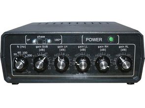
A block is found behind the census member shows the lower pass filter of the 3rd row. It has a 18dB octave slope. Delving frequency f01 is adjustable from 20Hz to 200Hz. In addition, the subwoofer contains a phase inertor which, serves to optimize the phase characteristic of the subwoofer versus phase satellite characteristics. The switch is used to set the phase shift 0 ° or 180 °. The last branch block is the gain setting circuit. You can set the potentiometer from -20dB to + 20dB. Subwoofer Crossover
Active Electronic Crossover Circuit Schematic
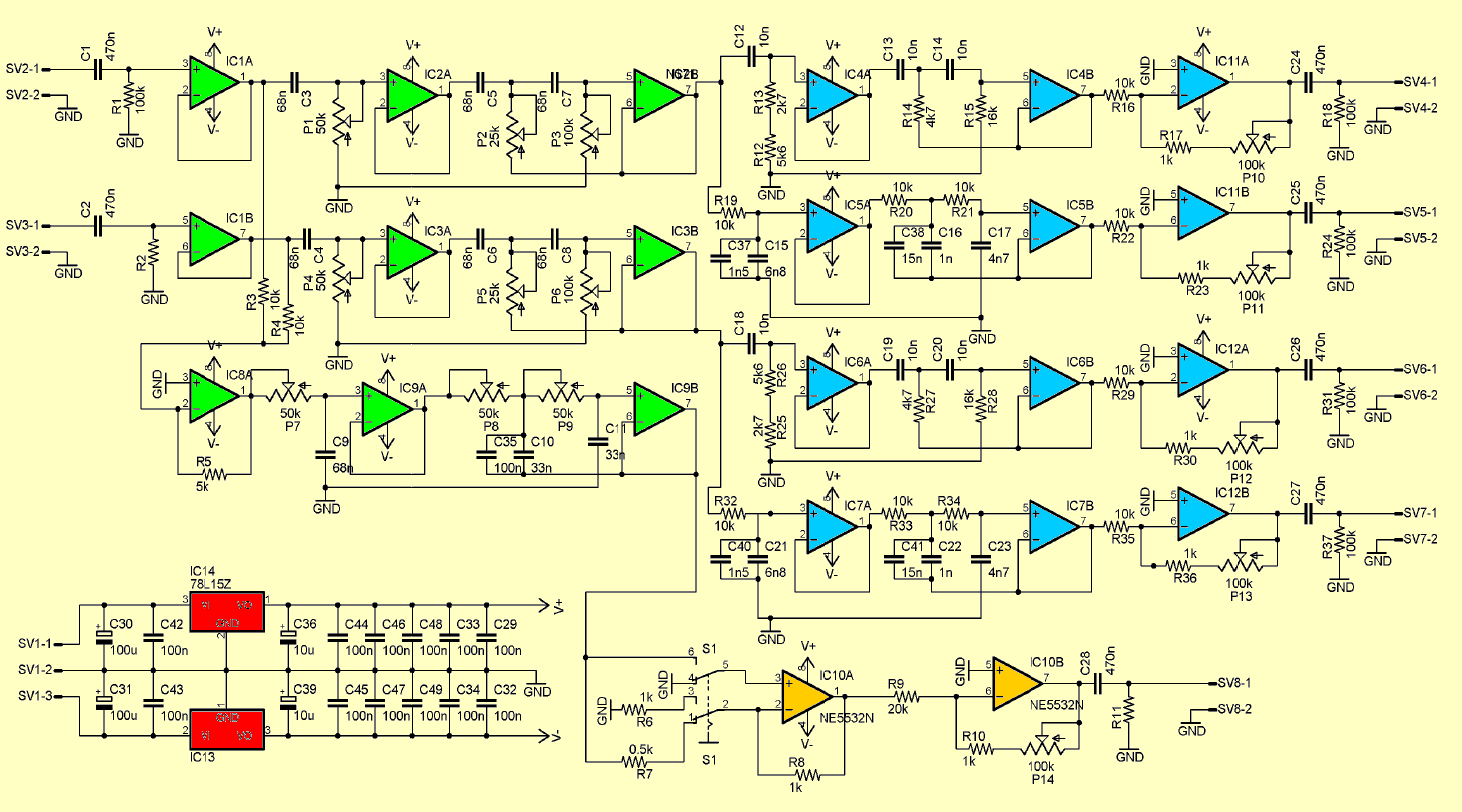
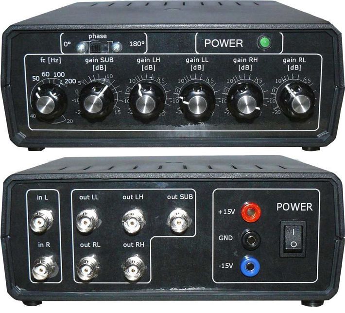
Both the right and left channel channels are the same. The first block shows as in the subwoofer branch of the 3 rd filter, the upper pass. Frequency f01 sa adjusts the subwoofer division frequency. The signal is further divided using the additional 2 bottom and top flow filters. Frequency decomposition is f02, which is fixed at approximately 1.97 kHz. It follows that signal satellites are divided into two channels, one of which transmits lower frequencies and the other higher. Each of these is then fed into blocks that are intended for setup profit. As with the subwoofer, the gain can be set within the range of -20dB to + 20dB. Each channel then has its own output. Together, therefore, there is a switch 2 outputs for each satellite and one for the subwoofer.
![]()
FILE DOWNLOAD LINK LIST (in TXT format): LINKS-26030.zip


Subwoofer Frequenzweiche 18dB 20Hz 200Hz
Subwoofer Frequenzweiche NE5532 Das hörbare Frequenzband liegt im Frequenzbereich 20 Hz bis 20 kHz. Es werden Signallautsprecher verwendet, die jedoch nicht in der Lage sind, das gesamte hörbare Band zu übertragen. Lautsprecher werden auch Breitband verwendet, das den größten Teil der Band aber nicht ganz überträgt. Sie haben immer noch ein Problem mit geringer Verzerrung, Minimaldirektionalität und ausreichender akustischer Leistung.
In dem Sub wird durch die Summe der Signale von rechts ein linker Kanal erzeugt. Manchmal wird das Eingangssignal nur einem Kanal zugeführt, aber es ist nicht mehr in der Lage, Geräusche zu erzeugen, die nicht für beide Calls gemeinsam sind und vom zweiten Kanal übertragen werden. Ein Block befindet sich hinter dem Zensusmitglied und zeigt den unteren Passfilter der dritten Reihe an. Es hat eine 18 dB Oktave. Delving Frequenz f01 ist einstellbar von 20Hz bis 200Hz. Darüber hinaus enthält der Subwoofer einen Phasen-Inertor, der zur Optimierung der Phasencharakteristik des Subwoofers im Vergleich zur Phase der Satellitencharakteristik dient. Mit dem Schalter wird die Phasenverschiebung 0 ° oder 180 ° eingestellt. Der letzte Verzweigungsblock ist die Verstärkungseinstellschaltung. Sie können das Potentiometer von -20dB bis +20dB einstellen. Subwoofer-Frequenzweiche
Circuit croisé de subwoofer 18dB
Circuit de croisement actif électronique Crossover de caisson de basses NE5532 La bande audible se situe dans la plage de fréquences de 20 Hz à 20 kHz. Des haut-parleurs de signal sont utilisés, mais ils ne sont pas capables de transférer la totalité de la bande audible. Les haut-parleurs sont également utilisés à large bande qui transmet la majeure partie de la bande mais pas la totalité. Ils ont toujours un problème de faible distorsion, de mini-directivité et de performances acoustiques suffisantes. Dans le sous est créé par la somme des signaux du canal droit et gauche. Parfois, le signal d’entrée est envoyé à un seul canal, mais il perd la capacité de créer des sons qui ne sont pas communs aux deux appels et sont transmis par le deuxième canal.
Un bloc se trouve derrière le membre du recensement montre le filtre passe-bas de la 3e rangée. Il a une pente d’octave de 18 dB. La fréquence de retombée f01 est réglable de 20 Hz à 200 Hz. De plus, le subwoofer contient un inerteur de phase qui sert à optimiser la caractéristique de phase du subwoofer par rapport aux caractéristiques du satellite de phase. Le commutateur est utilisé pour régler le déphasage de 0 ° ou 180 °. Le dernier bloc de dérivation est le circuit de réglage du gain. Vous pouvez régler le potentiomètre de -20 dB à + 20 dB. Crossover caisson de basses