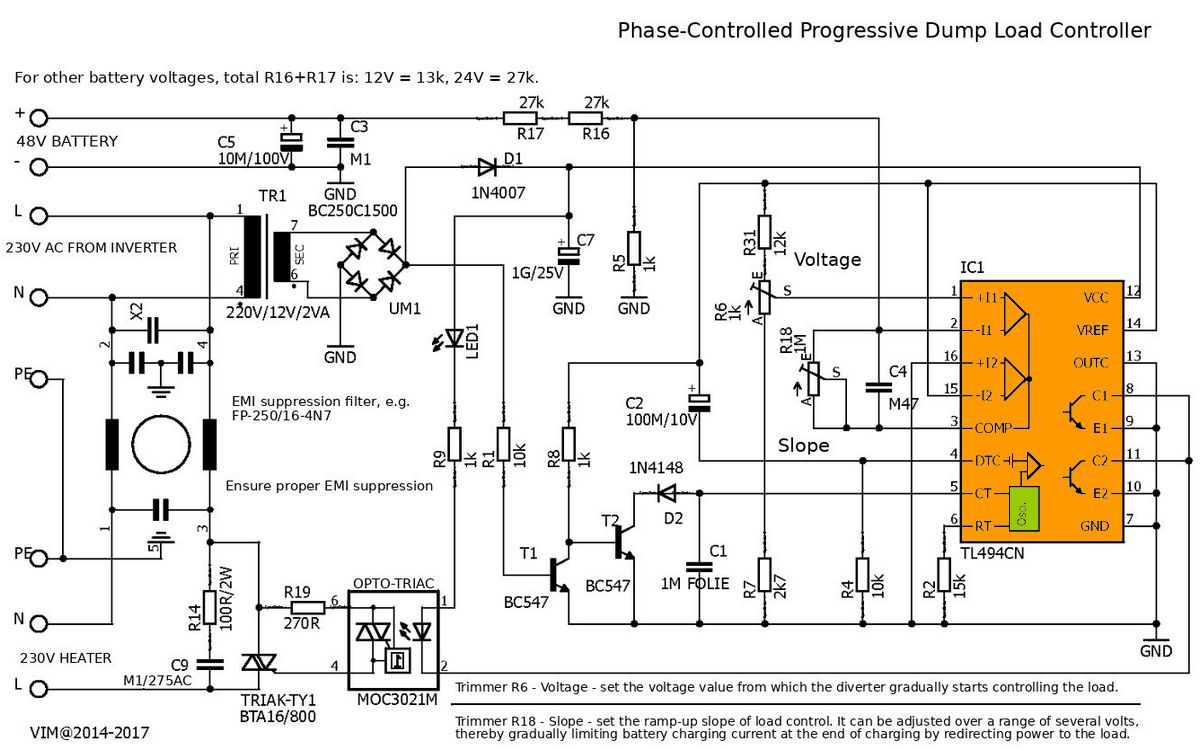
The phase-controlled photovoltaic excess energy router circuit gradually transfers the energy at the inverter’s 230V AC output to a resistive load when the battery voltage rises above the set level. This load is usually a boiler, water heater element, or similar ohmic heater. At the center of the circuit is the TL494CN, and on the output side there is a MOC3021 optotriac and a power triac.
Purpose of the Energy Router Circuit
Contents
- 1 Purpose of the Energy Router Circuit
- 2 Basic Operating Principle
- 3 Load Control with Battery Voltage
- 4 How Is the TL494CN Used in This Circuit?
- 5 MOC3021 and Triac Selection
- 6 230V Power Line and Resistor Connection
- 7 EMI Filter and Snubber Section
- 8 PCB Layout
- 9 Relationship with TY_Nab5
- 10 Adapting to 12V and 24V Systems
- 11 Initial Startup and Adjustment Recommendation
- 12 Safety Warnings
- 13 Common Mistakes
- 14 Technical Summary
- 15 General Evaluation of the Project
TL494 phase-controlled photovoltaic excess energy router circuit diagram
In off-grid or hybrid photovoltaic systems, when the battery approaches full charge, it is desirable not to waste the energy coming from the panels.
When the charge controller or inverter starts limiting power, the excess energy can be transferred to water heating through a controlled load.
This circuit is a phase-controlled AC load driver prepared exactly for this purpose.
In classic on-off relay systems, the load turns on suddenly and turns off suddenly.
This can create sudden current pulses at the inverter output, fluctuation in battery voltage, and a jagged behavior in the system graph.
The phase-controlled structure increases or decreases the power delivered to the 230V resistor more smoothly by changing the triac firing angle.
These types of circuits are not direct battery charge regulators. By monitoring the battery voltage, they route the excess energy to the heater on the AC side when the battery approaches the full charge level.
For those interested in solar energy and battery systems, solar energy battery charging and solar panel calculation topics are complementary resources for understanding the usage logic of this circuit.
Basic Operating Principle
There are two separate sides in the circuit. The first side is the low-voltage control section; here the battery voltage is measured, threshold and slope adjustments are made, and the TL494CN output is generated.
The second side is the 230V AC power section; here the triac is triggered at a certain point of the sine wave at the inverter output and adjusts the power going to the resistor.
The control board senses the voltage of the 48V battery bank through a resistor divider. If the battery voltage is below the set threshold, energy transfer to the 230V load does not start or remains at a very low level.
As the voltage rises above the threshold, the control voltage of the TL494 changes, the triac is triggered earlier, and the average power transferred to the resistor increases.
| Section | Main components used | Function |
|---|---|---|
| Battery voltage sensing | R16, R17, R6 trimpot | Reduces the battery voltage to a suitable level for the TL494 control input and adjusts the start threshold. |
| Slope / soft transition adjustment | R18 trimpot, C4 | Determines how quickly the load will increase and softens sudden on-off behavior. |
| Control IC | TL494CN | Generates triac drive timing with its comparator, reference, and oscillator blocks. |
| Isolation | MOC3021 | Provides optical isolation between the control circuit and the 230V triac gate. |
| Power switching | BTA16/800 or BTA140/800 suitable for the PCB | Controls the power on the 230V AC resistor line according to the phase angle. |
| Interference suppression | EMI filter, RC snubber, X2 capacitors | Reduces interference generated during triac switching and triggering moments. |
| Auxiliary power supply | Small 230V/12V transformer, bridge diode, filter capacitor | Supplies the TL494 and the low-voltage control section. |
Load Control with Battery Voltage
The main measurement point in the schematic is the battery voltage. For a 48V system, the R16 and R17 resistors are drawn as 27k + 27k.
The note states that the total R16 + R17 value should be changed for different battery voltages: approximately 13k can be used for a 12V system, and approximately 27k for a 24V system.
For a 48V system, the 54k total value is therefore logical.
The purpose here is to bring a similarly scaled measurement voltage to the TL494 input at different system voltages.
If the resistor divider is selected incorrectly, the adjustment range of the R6 trimpot will not fall into the proper point.
In this case, the circuit either starts loading too early or does not open the load sufficiently even if the battery voltage rises.
R6 Napětí Adjustment
In the other schematic, the R6 trimpot is marked as “Napětí”. This adjustment determines after which battery voltage the load will turn on.
For example, if loading is intended to start around 54V in a 48V LiFePO4 system, R6 is adjusted according to this point.
When making the adjustment, it is safer to use a current-limited laboratory power supply instead of a real battery.
The supply voltage is slowly increased, and the triac triggering behavior or load output is observed with an oscilloscope. In this way, it can be seen at which voltage the circuit starts cutting in.
R18 Strmost Adjustment
The R18 trimpot is “Strmost”, that is, the slope adjustment. This adjustment determines how quickly the load will be increased after the threshold is exceeded.
If the slope is set too steep, the circuit approaches the behavior of a relay system; the inverter suddenly sees a high load.
If the slope is set too soft, the excess energy cannot be consumed quickly enough and the battery voltage may rise more than necessary.
Therefore, R6 and R18 should be adjusted together. R6 determines the voltage at which loading will start, while R18 determines how the power will increase after this start.
How Is the TL494CN Used in This Circuit?
The TL494 is mostly known as an SMPS and PWM control IC. However, thanks to its internal reference, error amplifiers, oscillator, and output transistors, it can also be used in phase-controlled timing circuits.
Here, the TL494 generates the control signal that drives the MOC3021 depending on the battery voltage.
The TL494’s 5V reference output and error amplifier inputs compare the scaled voltage coming from the battery with the adjustment trimpots.
The oscillator section creates the time base with components such as C1 and R2. The output stage drives the optotriac LED at suitable times.
To become familiar with power and control circuits operating with the TL494, TL494 DC-DC CV CC circuit and TL494 IR2153 LM358 optocoupler test topics may be useful.
In this project, the TL494 does not manage a DC-DC converter; it manages phase-controlled AC load triggering.
MOC3021 and Triac Selection
A MOC3021 optotriac is used in the circuit. This component is different from the types that wait for zero crossing; it is suitable for phase control applications.
In phase control, the triac is not triggered exactly at the beginning of the sine wave, but with the desired delay. Therefore, zero-cross optotriacs such as MOC306x do not perform the same function here, because they try to turn on the triac near the zero crossing.
The power triac is shown as BTA16/800 in the schematic. In the Readme note, however, it is specifically stated that the used PCB is suitable for BTA140/800, not for BTA26/800.
Therefore, the pinout and package type must be checked according to the printed circuit board. When replacing the triac, not only the current and voltage rating but also the pinout and heatsink connection are important.
Triac Heating
A voltage drop of a few volts may occur across the triac during conduction. As the load current increases, this loss turns into heat.
For example, a 1kW / 230V resistive load draws approximately 4.3A current. The loss on the triac can reach a few watts. For loads of 2kW and above, a heatsink becomes mandatory.
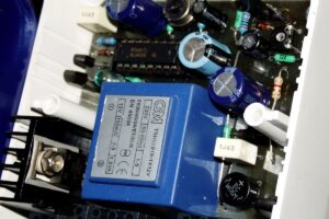
The Readme note states that ventilation holes were used in a small enclosure and that the enclosure felt cold in practice.
However, this observation should not be accepted as valid for every load. The triac temperature should be measured at the actual operating power, and if possible, it should be checked with a thermocouple or IR thermometer.
230V Power Line and Resistor Connection
There are 230 IN and 230 OUT connections on the PCB. The 230 IN side is the AC line coming from the inverter, and the 230 OUT side is the output going to the resistive load.
This circuit is not used to feed energy into the grid. The most correct use is a separate AC line supplied from the inverter output and going only to the boiler resistor.
In the forum notes, it is stated that this loading branch is reserved only for the boiler and is not connected to the distribution grid.
This is more correct in terms of safety and interference management. Since triac phase control cuts the sine wave, it can create hum, interference, radio frequency noise, or unwanted behavior in some devices connected to the same line.
This circuit should not be considered suitable for a motor, transformer, device with SMPS input, LED driver, or electronically controlled heater. The safest load type is an ohmic load such as a classic resistor, immersion heater, or boiler heating element.
EMI Filter and Snubber Section
The weakest side of triac phase control is interference. When the sine wave is cut from a certain angle and delivered to the load, the current waveform is distorted.
This distortion can spread as interference to the cables, inverter output, and receivers in the nearby environment.
In the schematic, a mains filter referred to as odrušovací filtr at the input, X2-class capacitors, common-mode chokes, and RC suppression components are used.
In the usage note, an Epcos B84111F0000B120 type suppression filter is mentioned. When selecting a filter, the current rating, operating voltage, and connection type must be suitable for the load.
Snubber components limit sudden voltage changes across the triac terminals. The capacitors here must be X2 safety class suitable for operation on the mains.
Random film capacitors or low-voltage capacitors should not be used.
PCB Layout
Phase-controlled excess energy router PCB copper traces and power line layout
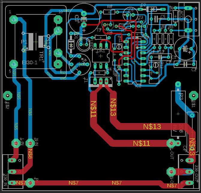
On the PCB, the low-voltage control section is concentrated on the left side, while the 230V power paths are carried with wide copper traces on the right side.
This separation is a correct approach. Still, the insulation distances on the 230V side, soldering quality, and internal enclosure layout must be checked carefully.
Wide copper areas used in the power paths are necessary to carry the resistor current.
If long-term high-power operation is planned, the PCB trace alone should not be considered sufficient; tin reinforcement, copper wire reinforcement, or external wiring with a suitable cross-section should be considered.
The topic of PCB trace current carrying and thermal calculation is directly related to this issue.
Relationship with TY_Nab5
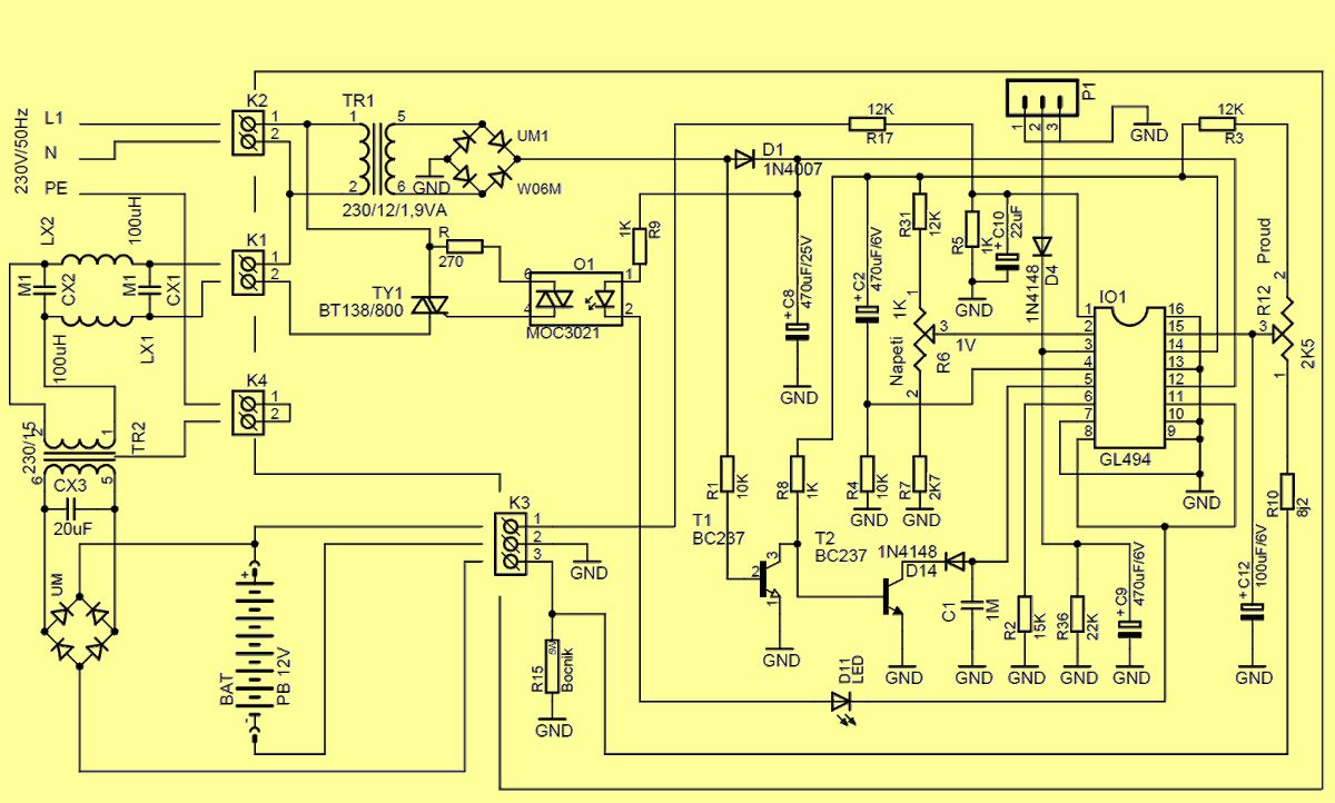
The TY_Nab5 document in the additional files shows that this circuit family is derived from a triac-based battery charge control circuit.
In TY_Nab5, there are a GL494/TL494 control IC, MOC3021 optotriac, BT138/800 triac, 230V/12V auxiliary transformer, and current sensing shunt.
In the original use, the triac was intended to manage the primary side of a powerful charging transformer with phase control.
The logic is similar in the phase-controlled excess energy router: a powerful 230V load is driven gradually through the triac.
The difference is that here the target is not to limit the battery charging current, but to transfer the excess energy at the inverter output to the resistor when the battery is full.
For similar triac-based battery charger examples, triac charger circuits for car batteries are also closely related applications.
Adapting to 12V and 24V Systems
The note in the schematic says that the total R16 + R17 value should be changed according to the battery system voltage.
In the 48V drawing, 27k + 27k is used. Approximately 27k total is recommended for 24V, and approximately 13k total for 12V. These values reduce the battery voltage to a range that the TL494 can measure.
When making the adaptation, it is not correct to change only these two resistors and use the circuit directly.
The R6 threshold adjustment, R18 slope adjustment, control circuit supply, load power, and inverter capacity must be tested together.
In 12V systems, the battery voltage range is narrower, so the adjustment becomes more sensitive.
Initial Startup and Adjustment Recommendation
- The control supply should be measured before connecting the triac and 230V load.
- The TL494 supply voltage and reference output should be checked.
- A current-limited adjustable DC source should be connected instead of the battery input.
- The voltage at which loading will start should be adjusted with R6.
- The MOC3021 drive signal or the chopped sine wave at the triac output should be observed with an oscilloscope.
- It should first be tested with a low-power incandescent lamp or a small resistive load.
- Before switching to the actual boiler resistor, the triac temperature and EMI filter heating should be measured.
- If the inverter power is lower than the connected resistor power, the system may be stressed.
In the forum notes, it is stated that 2 x 1kW resistors can strain a 2kW inverter, while they work more comfortably with a 4kW inverter.
This is practically important. Even if phase control can reduce the power, the current that the resistor can draw at full power must be suitable for the instantaneous and continuous power limit of the inverter.
Safety Warnings
In this circuit, 230V AC voltage, a high-current resistor line, and battery connection are present in the same system.
It is not a suitable beginner project for users without electrical knowledge.
Every connection on the mains side, fuse, cable cross-section, PE grounding, and enclosure insulation must be done correctly.
If a metal enclosure is used, protective grounding must be provided, and 230V terminals must be protected against touch.
Solder points under the PCB must not touch the enclosure. Depending on the triac model used, the triac heatsink may have to be electrically isolated.
Although isolated-tab models are available in BTA series, measurement and datasheet checks should be performed without relying only on the part code.
Triac phase control can generate radio interference. The EMI filter, short wiring, metal enclosure, correct PE connection, and snubber circuit should not be neglected.
If there is a transceiver, radio receiver, sensitive measurement device, or communication equipment nearby, the circuit should be tested under real load.
Common Mistakes
- Using a zero-cross optotriac instead of MOC3021 and causing phase control not to work.
- Installing triacs such as BTA16, BTA26, and BTA140 on the PCB without checking the pinout.
- Skipping the EMI filter or not selecting it with a suitable current rating.
- Not changing the battery voltage divider resistors according to the system voltage.
- Randomly turning the R6 and R18 trimpots while the load is connected.
- Selecting a boiler resistor power higher than the continuous power limit of the inverter.
- Keeping the triac heatsink too small and placing it in a closed enclosure without measuring temperature.
- Testing the circuit on a line connected to the distribution grid.
- Connecting SMPS, motor, or electronically controlled loads to this output.
Technical Summary
| Feature | Description |
|---|---|
| Circuit type | Phase-controlled excess energy router operating according to battery voltage |
| Typical use | Transferring excess energy in a photovoltaic system to a boiler resistor |
| Control IC | TL494CN / GL494 |
| Optical driver | MOC3021 random-phase optotriac |
| Power switch | BTA16/800 is shown in the drawing; according to the Readme note, the PCB is suitable for BTA140/800 |
| Control supply | Small 230V/12V auxiliary transformer and bridge rectifier |
| Battery system | 48V in the drawing; it can be adapted to 12V and 24V systems by changing the resistor divider |
| Start adjustment | The battery voltage threshold is adjusted with the R6 trimpot |
| Slope adjustment | The load increase characteristic is adjusted with the R18 trimpot |
| Output load | Resistive 230V load, for example a boiler heating element |
| Interference prevention | EMI filter, RC snubber, short wiring, and metal enclosure are recommended |
General Evaluation of the Project
The TL494-based phase-controlled excess energy router is a practical solution for transferring excess energy to water heating when the battery approaches full charge in off-grid photovoltaic systems.
It provides smoother power control compared to the relay-based on-off method. Especially when used on a separate inverter line reserved only for a resistive load, a functional structure emerges.
The weak side of the circuit is that, because it performs phase cutting on 230V, it requires attention in terms of safety and EMI.
It should not be used without the correct triac, a suitable heatsink, a good suppression filter, safe enclosure, and careful adjustment.
It is not a suitable project for those without electrical safety knowledge; however, for experienced users, it offers a useful circuit concept for utilizing excess energy.
Source: forum.mypower.cz/viewtopic.php?t=10717


