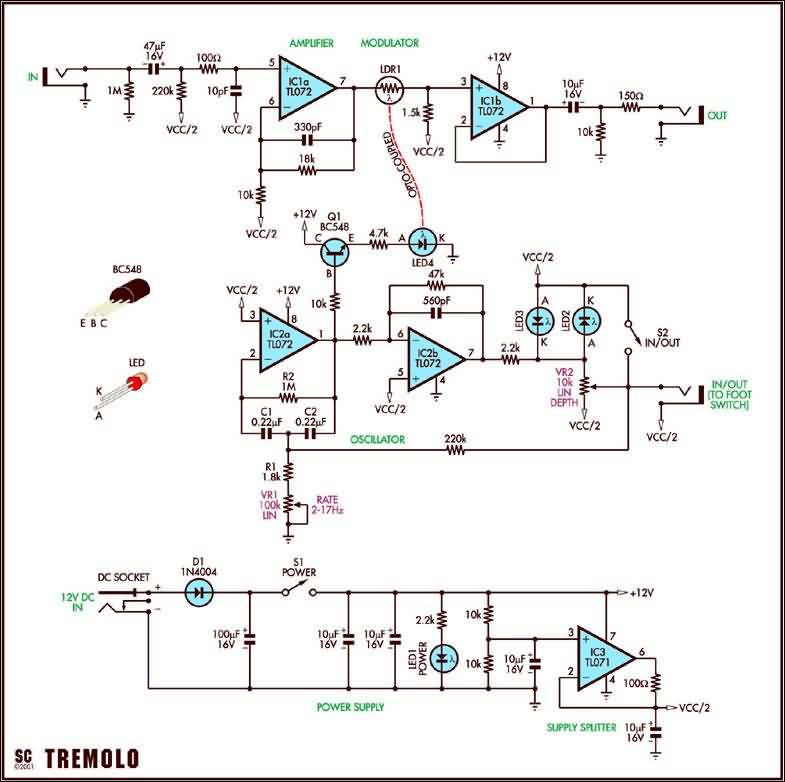
The effect circuit is based on tl072 and tl071 opamp ICs. “rate, depth” settings can be adjusted. You can operate it with a 12 volt dc adapter.
- Total harmonic distortion: 0.1% at 100mV in and @ 1kHz
- Signal to noise ratio: 108dB with respect to 1V input and 1k input loading; 112dB A weighted
- Maximum input before clipping: 1.2Volt RMS (12Volt DC input supply)
- Frequency response: 0.1dB at 20Hz; -3dB at 34kHz
- Signal gain: 1V in for 1V out with no tremolo modulation
- Tremolo frequency range: 2Hz to 17Hz
- Tremolo modulation depth: from 0% up to 80% modulation
- Average output level change: for 0-50% modulation -0.4dB at 50% modulation
Tremolo Effect Circuit Schematic
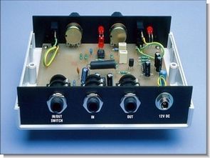
Tremolo Effect Project

Source: http://www.siliconchip.com.au/cms/A_102004/article.html
Guitar Tremolo Effect Circuit Opamp TL072 TL071 schematic pcb files alternative link:
Guitar Tremolo Effect Circuit Opamp TL072 TL071 ZIP File Password: 320volt.com


Adjustable Simple Metronome Circuit (Two transistor)
One very simple metronome circuit npn and pnp transistor and one capacitor potentiometer resistance buzzer can be connected to the audio output to speakers or headphones + 5v dc supply voltage can be
Bcxxx bdxxx transistors used for the different series can I try 2s945 (npn) 2sa733 (PnP) I used 47k resistors. 16v 4.7uF capacitor values can be altered in different hues 270k potentiometer clicks if you use the higher the value the lower the isis-metronome simple simulation
metronome circuit diagram