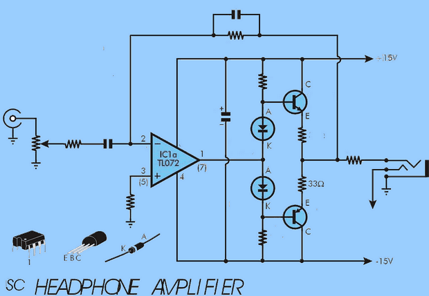
The circuit is based on the TL072 Op Amp and its output is powered by the bc338 and bc328 transistors. A simple and low cost circuit supply voltage +- 15 volts symmetrical. Each channel of the headphone amplifier uses an op amp that drives a complementary pair of transistors located in the overall negative feedback loop.
CD/DVD player output, tuner etc. There’s nothing to stop you from using this project as a general purpose headphone amplifier, as long as it’s powered by “line level” signals like
RIAA Preamplifier Performance
Output level: 90mΩ (max) into 8W headphone
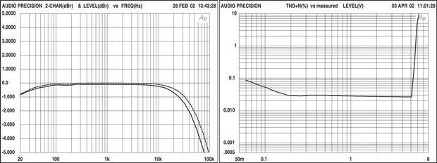
Frequency response: 0.5dB down at 30Hz and 20kHz
Input sensitivity: 0.83V RMS for full power
Signal-to-noise ratio: -95dB unweighted (20kHz 20Hz) regarding 500mV input signal
Separation Between Channels: 50dB from 20Hz to 10kHz
Source: http://www.siliconchip.com.au/cms/A_30588/article.html
Headphone Amplifier schematic PCB files alternative link


Automatic 12V 24V Solar Panel Charger Circuit
Solar Battery Charger Circuit MOSFET power transistor used in the MTP2955 charge and charge status LEDs can observe with 0:33 in the circuit diagram? TEXT trying to SEA could not find any explanation to account for this resistance is probably 0.6 v divided by current limitation I (to be current)
Solar Panel Charger 12V 24V