Active subwoofer filter circuit based on TL072 Opamp is designed for use with Power amplifier with good parameters (narrow frequency response). The transition band of the filter is between about 10Hz (bottom) and 80Hz. + -12v symmetrical Zenerli regulated circuit Max. input voltage + – 38VDC
There are PCB and diagram drawings, material list prepared with eagle cad of active bass filter circuit. In addition, there is SMD version of PCB drawing.
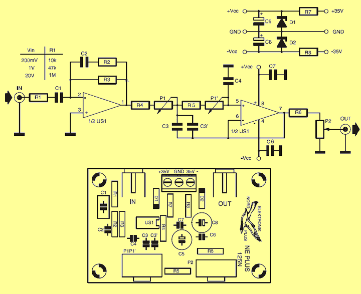
If you get the input audio signal from the Direct amp output, you need to change the R1 resistance according to the chart in the diagram.
Active subwoofer filter circuit diagram
Source: pokec.azet.sk
FILE DOWNLOAD LINK LIST (in TXT format): LINKS-26624a.zip


TL072 Filtre subwoofer actif 80 Hz-250 Hz
Le circuit de filtre de subwoofer actif basé sur TL072 Opamp est conçu pour être utilisé avec un amplificateur de puissance avec de bons paramètres (réponse en fréquence étroite). La bande de transition du filtre est comprise entre environ 10 Hz (en bas) et 80 Hz. + -12v symétrique circuit régulé Zenerli Max. tension d’entrée + – 38VDC
Il y a des schémas de circuits imprimés et de diagrammes, une liste de matériaux préparée avec un cadran Eagle du circuit de filtre de basses actif. De plus, il existe une version SMD du dessin PCB.
Si vous obtenez le signal audio d’entrée de la sortie de l’ampli direct, vous devez modifier la résistance R1 conformément au tableau du diagramme.
Schéma du circuit de filtrage du caisson de graves actif