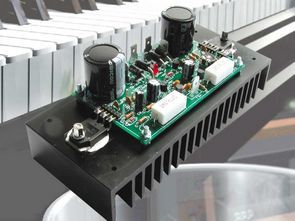
Darlington Transistor TIP147 TIP142 Amplifier Circuit
– Output power @ 4 ohm: 100 W;
– Output power @ 8 ohms: 70 W;
– Distortion (THD @ 1 kHz / 10 W): 0.02%;
– S / N ratio: 115 dB;
– Bandwidth: 3 Hz ÷ 200 kHz;
– Sensitivity: 600 mVeff;
– Supply voltage: 2×30 Vac;
– Absorbed current: 2 A per branch.
The mini hi-fi and use them as the main stereo system, we must not forget that a good system for listening to music is quite different: enough listen to one of the commercial products not just on the shop counter but also in a domestic environment, to realize that it sounds badly, that he is missing something. Unfortunately, precisely because currently traditional hi-fi are cassettes, CD player, tuner)
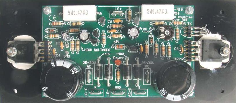
If necessary, adjust RV1 until a value of about 14 millivolts, which correspond to an absorption of the circuit of the order of 30 mA. Remove tension and remove the tester and short circuit at the entrance: the amplifier is ready for use.
The two elements of power in question they are darlington integrated, that is, each of them contains two bipolar transistors of the same polarity in configuration darlington: common collectors and the emitter of the first connected at the base of the second. Those of us employed are TIP142 and TIP147, respectively NPN and PNP and constitute a complementary couple; the choice stems from the high earnings
in current than a darlington can give and that allows us to simplify the amplifier while saving a pair of transistor drivers otherwise necessary to give to basics of common BJT the necessary current. Each of our elements guarantees a gain in current (hFE) of at least 1,000 to 4 volts of Vce and 5 A of collector current; also supports Vce in 100 V interdiction (and that is fully compatible with our needs, since the circuit works with a total of 80 volts) e a current of 10 A, dissipating a maximum of 125 W at 150 ° C temperature junction.
Darlington Transistor Amplifier Circuit Schematic

Once assembly is complete, it is necessary calibrate the amplifier: for the purpose short-circuit the entry points and bring the trimmer cursor to half stroke; connect to the circuit on secondary of a transformer from 120 ÷ 150VA 2x28VAC or 2x30VAC: the extremes go to the AC points and the socket to AC0, otherwise you risk not watch the amplifier work. After that, with a tester ready to the measurement of direct voltages with full scale of 2 ÷ 5 volts read the tension across the resistance R19 or R20: in the first case to the electrode connected to the output goes the negative tip; In the second, the positive one.
FILE DOWNLOAD LINK LIST (in TXT format): LINKS-26510b.zip


TIP147 TIP142 Amplificateur Circuit 200W Musique
Circuit d’amplification du transistor TIP147 TIP142 de Darlington
– Puissance de sortie @ 4 ohms: 100 W;
– Puissance de sortie @ 8 ohms: 70 W;
– Distorsion (THD @ 1 kHz / 10 W): 0,02%;
– Rapport S / B: 115 dB;
– Bande passante: 3 Hz ÷ 200 kHz;
– Sensibilité: 600 mVeff;
– Tension d’alimentation: 2 × 30 Vac;
– Courant absorbé: 2 A par branche.
La mini chaîne hi-fi et les utiliser comme système stéréo principal, il ne faut pas oublier qu’un bon système pour écouter de la musique est assez différent: assez écouter l’un des produits commerciaux non seulement sur le comptoir de la boutique mais aussi dans un environnement domestique , pour réaliser que ça sonne mal, qu’il lui manque quelque chose. Malheureusement, précisément parce que les chaînes hi-fi traditionnelles sont actuellement des cassettes, un lecteur CD, un tuner)
I am very much interested in this amplifier circuit and I want to build on for my self so Please can you give the value of the resistors, capacitors and other components? Also your Zip file cannot open.
thank you.
Hi, all information and files are in zip (pcb, part list) install latest version winrar https://www.rarlab.com/download.htm zip file password: 320volt.com
Hello! Please, if you are so kind, could you indicate the measurements of the PCB? height x width.
thank you!!!
Hello,
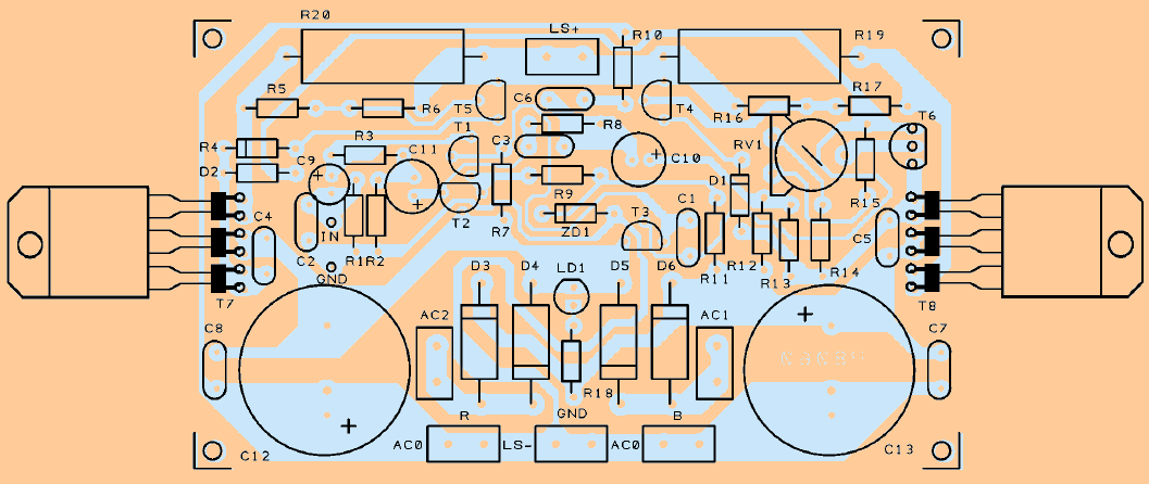
pcb size; 120x82mm (pcb.tif 300dpi)
https://youtu.be/fZTVt6YmVMM?t=2582
Tanks Gevv!!!!!!!!!!!