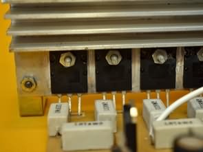
The output transistors MJL21194 are of great power and performance. They must be very well adjusted with through screws, washers and nuts and properly insulated from the heatsink with mica insulators. Remember to use silicone grease and tighten the screws very well, so that the heat is transmitted from the transistors to the heatsink. After screwing them to the heatsink, verify that they have been isolated from the heatsink. This is done by placing the multimeter in continuity and place one end of the multimeter in the sink and the other in the transistor collector, which is the pin or terminal of the center. You should not mark anything or infinity (a 1 on the left).
NOTE: The original power transistors are low gain. Therefore, if you use transistor MJL21194, you must have a maximum hFE or gain of 40. If you do not get these transistors you can use the 2SC5200, but you should also lower the transformer voltage to 45x45VAC. So the maximum that will be achieved is a power of 400W.
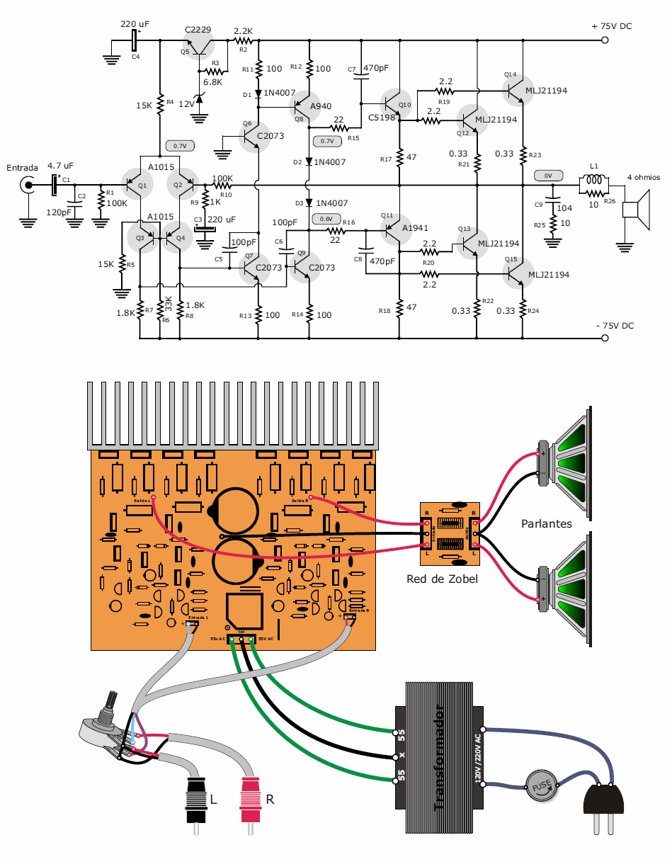
It is important to use a diode bridge of at least 25 amps. It does not mean that all those amps are going to pass through the bridge, but if a bridge is placed that only supports the amps used by the amplifier, it can heat up a lot, generating unnecessary heat that can dry the capacitors from the source until they reach to the point that it is necessary to change them for bad rectification.
The capacitors of the source can be at least 6,800 uF. The optimum is to use 10,000 uF and thus ensure a good rectification that results in a good response of high volume bass and clean sound.
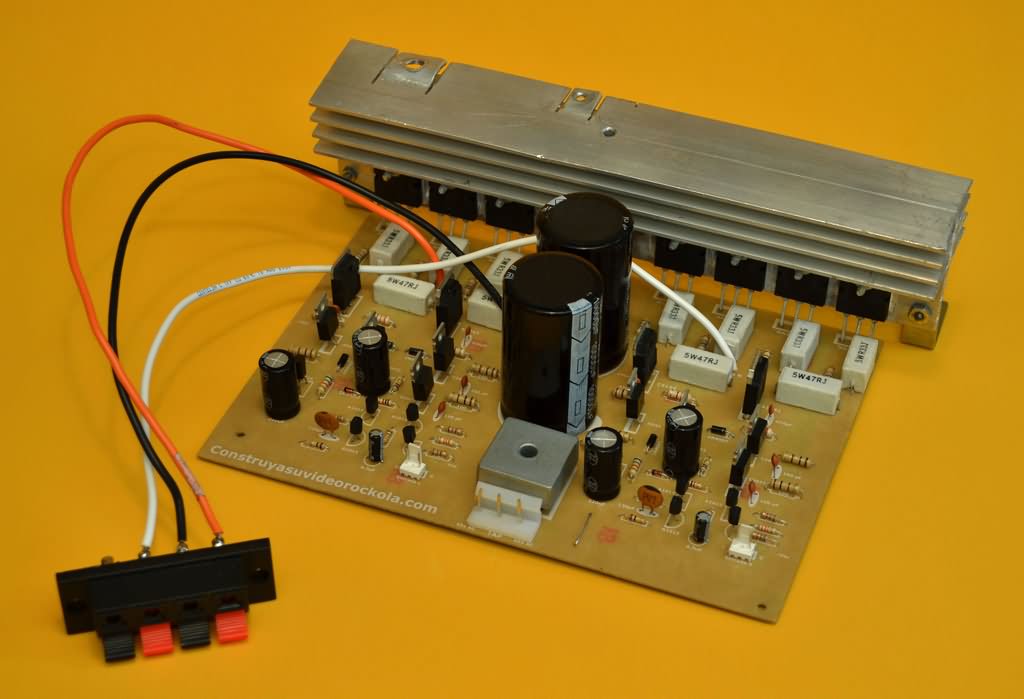
Source: construyasuvideorockola.com
FILE DOWNLOAD LINK LIST (in TXT format): LINKS-26087.zip


Lighting Circuit the Staircase
Lighting Circuit the Staircase
The aim of the project is to create a control unit, a controller, for the purpose of lighting the staircase. Stairs, respectively. each staircase is illuminated by an LED strip. The lighting responds to passing people and adequately evaluates the ambient light level. Parameters such as light time, light speed, length of light shine, etc. are adjustable.
Realization of Hardware
The controller is implemented on a double-sided printed circuit board. The core of the controller is 8bit. ATmega16 microcontroller, which is programmed via ISP interface (used by AVR Dragon programmer). There are 5 trimmers attached to the MCU to set the following parameters:
TR1 – Lighting intensity activation setting (related to ambient light level)
TR2 – Adjust the brightness manually
TR3 – Speed of gradual lighting
TR4 – The time of the light after the whole staircase is lit.
TR5 – Adjusts the brightness when lighting is on