
A Class D amplifier circuit designed for bass guitar. In addition, bass-guitar-specific tone-shaping Equalizer options and a preamplifier are available. More than 150W of power was obtained.
When the amplifier is Class D, there is an expectation of high power; I do not know whether it is worth implementing in terms of power. In fact, the HIP4081 is open to development, and very high power levels can be obtained with a stronger inductor and MOSFETs. The author already targeted 100W and obtained more than 150W of power 🙂
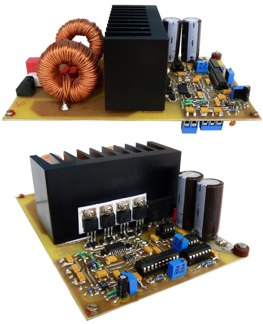
The amplifier panel design is very good; in addition, the bass guitar preamplifier, Equalizer, and Soft-start circuit can be used with different amplifiers.

Frequency Characteristics of the Bass Guitar and Preamplifier Design
Contents
The frequency range of a bass guitar is generally around ~30 Hz – 10 kHz (slightly wider in 5-6 string models). In passive bass guitars, the output level is typically ~100 mV, while in active basses it can be ~500 mV and above.
Therefore, the following features were focused on in the preamplifier:
- High input impedance (thanks to JFET transistors)
- Separate inputs for passive and active bass guitar
- 3-band active EQ + passive fixed-sharpness options
- Selectable frequency points in the mid frequencies
- Tube-like mild saturation (overdrive) character of the JFETs (pleasant distortion of the desired type)
The designed preamplifier schematic was tested in PSPICE simulations and implemented.

Class D Modulator and Main Components
Modulation signal generator: MAX038 (0.1 Hz – 20 MHz range; the circuit recommended in the datasheet file for a clean sine wave was used.
Error amplifier: Linear Technology LT1358 (high slew rate, wide bandwidth, low offset)
MOSFET driver: Intersil HIP4081 (ideal for full-bridge, bootstrap support, dead-time adjustment)
Dead-time adjustment can be precisely adjusted with a 220k trimpot. In this way, the risk of shoot-through (two transistors remaining on at the same time) is minimized.
Power Supply Design
300 VA toroidal transformer (custom-made, 40 V secondary)
Bridge diode + large heatsink
Filtering: 2 × 4700 µF + 2 × 1000 µF parallel electrolytic + ceramic/film bypass capacitors
Soft-start circuit (inrush current limiting – 50Ω / 5 W resistor group + relay)
In this way, the transformer and capacitors are protected from excessive current shock at initial power-up. At the output, it is ~55-57 VDC with no load, and it does not drop below 50 V even under full load.
The target was 100W, but more than 150W of power was obtained in the prototype. Higher power is possible, but long-term THD and efficiency measurements under full load have not yet been performed.

![]()


