The aim of the project is to create a control unit, a controller, for the purpose of lighting the staircase. Stairs, respectively. each staircase is illuminated by an LED strip. The lighting responds to passing people and adequately evaluates the ambient light level. Parameters such as light time, light speed, length of light shine, etc. are adjustable.
Realization of Hardware
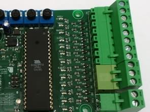
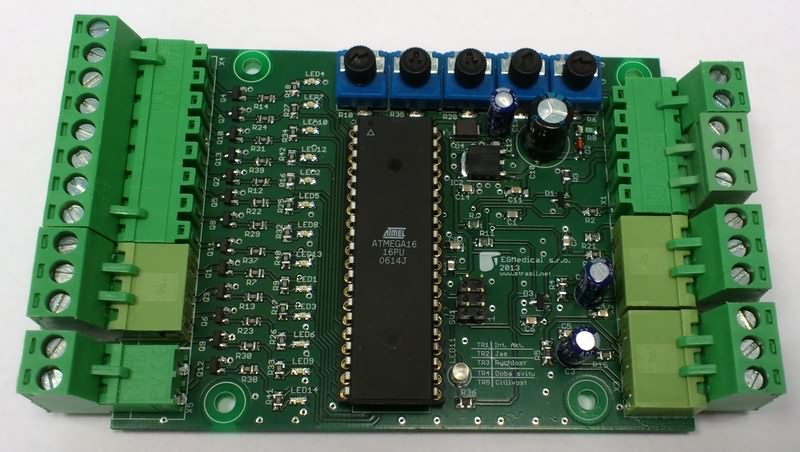
The controller is implemented on a double-sided printed circuit board. The core of the controller is 8bit. ATmega16 microcontroller, which is programmed via ISP interface (used by AVR Dragon programmer). There are 5 trimmers attached to the MCU to set the following parameters:
TR1 – Lighting intensity activation setting (related to ambient light level)
TR2 – Adjust the brightness manually
TR3 – Speed of gradual lighting
TR4 – The time of the light after the whole staircase is lit.
TR5 – Adjusts the brightness when lighting is on
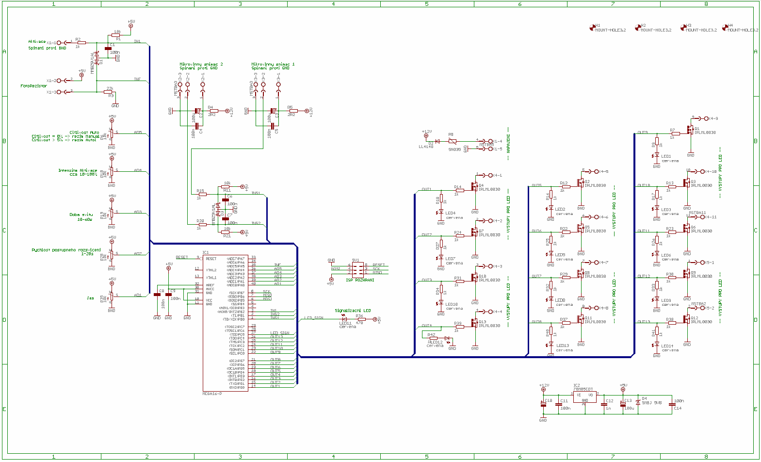
Furthermore, a photoresistor is connected to the MCU, which senses the ambient light value. As a result, the illumination does not activate at a value less than the TR1 trimmer. Switching itself and starting the lighting cycle is initiated in two possible ways. First using manual activation input AKT (switches against GND). The second option is to use ultrasonic sensors. These are located at both ends of the staircase and generate an activation signal when the motion is detected at the beginning of the staircase to start the light cycle.
The staircase has 13 steps and each is backlit with an LED strip (the supply voltage is 12V). Powering of the strips is ensured by switching of unipolar transistors IRLML0030. All tapes are connected by their positive power conductors (switching against GND). The MCU is powered via a 5V stabilizer.
Microcontroller Software implementation
The software was written in AVR Studio v4.18 in C language. The resulting uploaded * .hex file is about 12kB in size. The run of the program in the MCU is clear from the flowchart in Figure 3. After connecting the power supply, the individual ports are initialized, the interrupt masks are set and the necessary variables are loaded. Also, a timer is generated that generates a control signal to generate a software PWM signal for the required 13 channels – increment is performed in an interrupt. The set repetition rate for generating the PWM signal is 250Hz, but the maximum frequency is about half that of the ALU interruption.
This was only possible when the “speed” optimizations were turned on when translating the program. In other optimizations, the generated PWM signal was much slower. The whole is due to the large number of PWM channels (13). The dependence of the number of PWM channels on the real generated PWM signal rate was experimentally verified. The program continues on a branching condition where, when inactivated from the MW sensors (and also the ACP input), the A / D converters are read out, which reads the values set using the TR1 to TR5 trimmers and the photoresist. In case one of the sensors is activated, the values from the A / D converters are processed and the cycle of switching on the individual tapes starts according to the selected direction and mode. After completing this task, the program jumps to the branching condition again.
From the user’s point of view, running the program then has the following character: When the AC input is activated (for example, a connected switch), all LED strips are lit by gradually adding brightness. Once the LED strips are in the set lighting level (trimmer TR2) they are in this state for the set time (trimmer TR4). After this time, they all go out once again. When activated from the microwave sensor, the ambient light value is first compared with the value set by the TR1 trimmer. If the ambient light level is less than the set limit, the individual tapes are gradually switched on consecutively. The lighting direction is determined by the microwave sensor. The speed of lighting is influenced by TR3 trimmer and the intensity of maximum light is influenced by trimmer TR5. The tapes then light up again for the time set by TR4 and all of them dim at the same time until they go out completely.
The presented prototype is fully functional and has been successfully installed. The microcontroller control program could be further optimized to achieve better PWM repetition rate results. For a larger number of LED strips, a more powerful core MCU would be appropriate. Changing the number of LED strips would then be done by simply changing one value at the beginning of the program where it is defined. The switching transistors still have sufficient power reserve – they can be used for voltages up to 30V and a current of 5.3A. Thus, it is not necessary to control the LED devices only, but also other pulse-modulated power devices.
FILE DOWNLOAD LINK LIST (in TXT format): LINKS-26091.zip


Stereo Amplifier Of 500 Watts Quasi Complementary
Stereo Amplifier Of 500 Watts Quasi Complementary
The output transistors MJL21194 are of great power and performance. They must be very well adjusted with through screws, washers and nuts and properly insulated from the heatsink with mica insulators. Remember to use silicone grease and tighten the screws very well, so that the heat is transmitted from the transistors to the heatsink. After screwing them to the heatsink, verify that they have been isolated from the heatsink. This is done by placing the multimeter in continuity and place one end of the multimeter in the sink and the other in the transistor collector, which is the pin or terminal of the center. You should not mark anything or infinity (a 1 on the left).
NOTE: The original power transistors are low gain. Therefore, if you use transistor MJL21194, you must have a maximum hFE or gain of 40. If you do not get these transistors you can use the 2SC5200, but you should also lower the transformer voltage to 45x45VAC. So the maximum that will be achieved is a power of 400W.
Circuit d’éclairage de l’escalier
L’objectif du projet est de créer une unité de contrôle, un contrôleur, pour l’éclairage de l’escalier. Escaliers, respectivement. chaque escalier est éclairé par une bande LED. L’éclairage répond aux passants et évalue adéquatement le niveau de lumière ambiante. Des paramètres tels que le temps d’éclairage, la vitesse d’éclairage, la durée de brillance de la lumière, etc. sont réglables.
Réalisation de matériel
Le contrôleur est implémenté sur une carte de circuit imprimé double face. Le cœur du contrôleur est 8 bits. Microcontrôleur ATmega16, qui est programmé via l’interface ISP (utilisé par le programmeur AVR Dragon). Il y a 5 trimmers attachés au MCU pour définir les paramètres suivants:
TR1 – Réglage d’activation de l’intensité lumineuse (lié au niveau de lumière ambiante)
TR2 – Ajustez la luminosité manuellement
TR3 – Vitesse d’éclairage progressif
TR4 – Le temps de la lumière après que tout l’escalier est allumé.
TR5 – Règle la luminosité lorsque l’éclairage est allumé