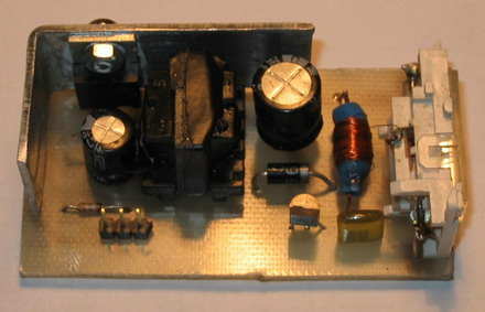
The inverter is constructed with the use of a small transformer core coming from the ATX power supply. Can be used with the inverter transformer stand-by or transformer control transistors kluczującymi. From the original core, delete the original winding and wind new 14zw Order code. original, five with in Order code. secondary and 350 with in the secondary winding
You should also check whether the column is the central core air gap. if it does not have to be sanded down one of the columns of the central core. The inverter has an output voltage stabilization at 320V which causes wide supply voltage range. The inverter is working correctly from 4V voltage With a supply voltage of 12V repetition frequency of flashes can occur 10 times a second. (10Hz)!
![]()
![]()

Half of the computer ATX power supply transformer used ee16b stand each other transformers can use the same PC power supply transformers with different codes are showing up 🙂 stantby portion size and transformer less you get hold enough


Microchip PIC16F, PIC18F Development Boards
This is a two-in-one PIC programmer and Experiment board for 40 pin PIC Micro devices.It easy to developt your program without insert/remove PIC micro.You just programming your code and then download to this board without any programmer .This board interface with parallel port.This board supports for PIC16F,PIC18F 40 pin devices .