Electric motors, in addition to many obvious advantages, also have some disadvantages. One of them is the consumption of a much higher current during start-up compared to the current consumed during normal operation, which can overload the power supply.
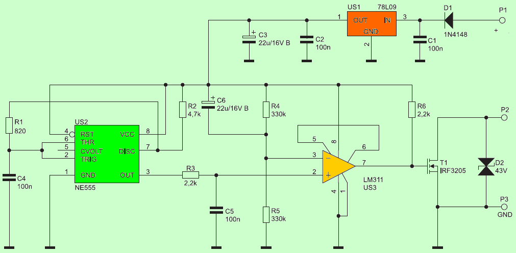
The schematic diagram of the “soft start” system is shown in figure. The multivibrator with the 555 timer IC system works in its typical application and generates a square wave with a frequency of about 2.2 kHz and a filling of about 85%. A circuit consisting of a resistor R3 and a capacitor C5 100NF is an integrating circuit that, by integrating the rectangular waveform, forms a quasi-triangular waveform from it.
Its shape is not important, it only has a clearly sloping rising and falling slope. In this form, this signal goes to the non-inverting input of the LM311 comparator. To its inverting input is connected a voltage divider giving a voltage of about 4.5 V. The C6 22UF capacitor means that when the power is turned on, the voltage is almost equal to the power supply (78L09 9 V), after which it slowly drops to the nominal value.
The comparator, working in an open feedback loop, is characterized by enormous gain, which results in rectangular signals with very steep slopes. By “comparing” the decreasing voltage at the inverting input and the triangular waveform at the non-inverting input, a rectangular signal with a filling increasing from zero to 100% is obtained.
Soft Start Circuit Schematic
Since the charging capacitor plays a key role in determining the fill, it should not come as a surprise that the shape of this curve is exponential. After approx. 7 seconds from applying power to the input + supply, the filling is 100% and the MOSFET IRF3205 transistor with the N channel is always open.
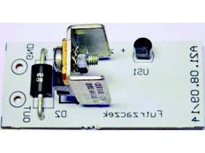
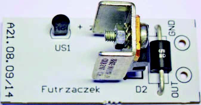
The circuit is assembled on a single-sided 23 mm × 50 mm printed circuit board, the assembly diagram of which is shown in Figure 3. All components, except for T1 transistor and D2 transil, are surface mounted. It is recommended to screw a small heat sink to the transistor. Supply voltage from 12 … 35 V; power consumption approx. 10 mA.
After replacing the transistor with another copy, you can control motors with higher power consumption and / or higher power supply. It is important that the power supply for the system is within the given range, so it can be routed from a separate power supply. With elements used in the model system, you can control motors with a voltage of up to approx. 40 V and a current of up to approx. 20 A, due to the power lost on the transistor. It is recommended to thicken the paths going to the leads of its drain and source.
The presented module can be used not only to operate engines. It will also be used when starting light bulbs or other receivers that are not served by current surges generated at power-up. The rise time of the filling at the output can be adjusted by changing the capacitance of the C6 capacitor and / or the resistance R4 330K and R5 330K remembering that they have the same value.
![]()
FILE DOWNLOAD LINK LIST (in TXT format): LINKS-26307.zip


Circuit de démarrage en douceur pour les moteurs à courant continu
Les moteurs électriques, en plus de nombreux avantages évidents, présentent également certains inconvénients. L’un d’eux est la consommation d’un courant beaucoup plus élevé au démarrage par rapport au courant consommé en fonctionnement normal, ce qui peut surcharger l’alimentation.
Le schéma de principe du système de «démarrage progressif» est illustré sur la figure. Le multivibrateur avec le système IC 555 timer fonctionne dans son application typique et génère une onde carrée avec une fréquence d’environ 2,2 kHz et un remplissage d’environ 85%. Un circuit composé d’une résistance R3 et d’un condensateur C5 100NF est un circuit d’intégration qui, en intégrant la forme d’onde rectangulaire, en forme une forme d’onde quasi triangulaire.
Sa forme n’est pas importante, elle n’a qu’une pente montante et descendante clairement inclinée. Sous cette forme, ce signal va à l’entrée non inverseuse du comparateur LM311. À son entrée inverseuse est connecté un diviseur de tension donnant une tension d’environ 4,5 V. Le condensateur C6 22UF signifie que lorsque l’alimentation est activée, la tension est presque égale à l’alimentation (78L09 9 V), après quoi elle baisse lentement à la valeur nominale.
Le comparateur, fonctionnant dans une boucle de rétroaction ouverte, se caractérise par un gain énorme, qui se traduit par des signaux rectangulaires avec des pentes très raides. En «comparant» la tension décroissante à l’entrée inverseuse et la forme d’onde triangulaire à l’entrée non inverseuse, on obtient un signal rectangulaire avec un remplissage croissant de zéro à 100%.