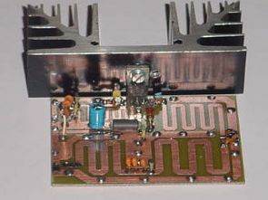
PLL RF amplifier, rdvv, cod, receiver, transmitter circuit and PCB drawings of many of the applied material’s information
Examples PLL RF transmitter circuits
Liste;
Amplfifier;
Absorptie-Dip-Frequentiemeter 75-225MHZ
met BLY87_88_89
100Watt (BLV36)
100mWatt – 22 Watt (BGY33 or 133)
10mWatt – 5watt (mrf237)
10mWatt – 6Watt Profline (MicroStripline BFR91&BFR96&2SC1971)
10mWatt – 8Watt Profline (BFR91&BFR96&2SC1971)
150-Watt (BLF177)
150WattMicroStripline (BLX15)
15Watt (2N3553 & 2N3632)
15Watt (SRF1024)
25Watt (2SC1971&1946A)
28Watt MicroStripline (2SC1946A)
2KW (QB 7.51750)
300 Watt (BLF278)
35Watt (SD1272)
40Watt (2SC1971 & mrf240)
45Watt (mrf238)
50Watt (BLW-60)
5Watt (SD1127)
6Watt MicroStripline (2SC1971)
80Watt (QQE0640)
90Watt (mrf245)
Senderbau 150-Watt (BLF177)
BF-900 Oscillator (VFO)
ERDS
FRM – PLL-Unit (CD4059)
FRM PLL-Unit (BF199 & 4059)
Grid Dipper 40673
PSU Fixed 50 Volt – 10 Amp
PSU Fixed 50 Volt – 7 Amp
Paradise Electronics – 4Watt – PLL ( Heerde Blikje)
RDVV 1W – HV
RDVV 1Watt – 2004
RDVV 300mWatt
RDVV 8Watt – 2004
RDVV Display
RDVV PLL-Unit
SPI PLL
Stentor 5Watt
Stereo Coder ;
14 x Sample
8 x Sample v5.1
9601
Elektuur
FRM
MyRds.fr.fm
NJM2035
SPI
Transmitter;
10Watt
150mWatt + PLL
15Watt (QQE0312) + PLL
15Watt (QQE0312)
1Watt (Veronica)
25watt
5Watt (Veronica)
5Watt + PLL(Veronica)
DZ 8410
Source: http://www.3-mtr.info/shareware/
FILE DOWNLOAD LINK LIST (in TXT format): LINKS-10329.zip
Published: 2010/05/16 Tags: analog circuits projects
Metal Detector Circuit PIC12F683 Microcontroller
With the metal detector. metal detector circuit PIC12F683 PIC will be an example in making a simple application software prepared by the micro c complier. Metal coil is used as a sensor from 10uH coil 300uh ….. LED lights when metal is giving approximation. Metal Detectors circuit supply 5 volts DC
Metal Detector