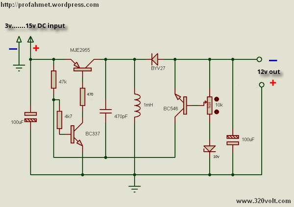
This circuit is an example of a simple Buck-boost converter circuit. By applying the input voltage from 3v to 15v outlet will receive a fixed value that you set. Determines the minimum output voltage of the zener 10v. You can set the output with 10k pot. You can use it to get a negative voltage you apply her to.
DC DC Converter Schematic


LCD Display PIC16F877 Nicd Nimh Battery Charger Circuit Digital Power Supply
Ni-cd, Ni-mh battery charger as a power supply used in digital circuit PIC16F877 microcontroller source software used and the file’s schema.
Isis an old file is not available to work. If you re prepared according to the scheme will operate in isis. Output voltage is adjusted with the pot. As a follower circuit the battery while charging current is running. If you choose one Ampere 1 wherein the charge in the battery if you connect five pieces in series you connect the battery. 1 amp charger automatically adjusts voltage and current remains constant. Choose different currents relays.
Battery Charger PIC16F877