PT (Princeton Technology Corp..) Series integrated materials in terms of quality not first class but for popular applications, especially for sound systems they have developed an integrated and quite talented, especially Chinese goods a lot of noise in the system PT series audio control ICs are used.
PT2350 circuit made with 2-channel sound, volume control left, right and subwoofer output filter has been specifically designed for 2 +1 amp circuit. Operating voltage from 20v dc 12v dc 10v … you can run with.
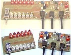
In addition to the 6-channel audio input also added ddevre these inputs can be controlled with the key
PT2350 Tone Control Subwoofer Cross-Over Low Pass Filter IC
PT2350 is a tone control subwoofer cross-over low pass filter chip utilizing CMOS Technology. It features a tone control range of + 10dB (50Hz, 4 KHz) and subwoofer low pass filter of the second order Sallen Key Design. The roll-off point can be adjusted by changing the value of the external capacitor. Pin assignments and application circuits are optimized for easy PCB Layout and cost saving advantages.
CMOS Technology
2-Channel Input
3-Channel Output (Including 1 stereo Output and Subwoofer Output)
Low Total Harmonic Distortion (THD<0.01%, Subwoofer THD<0.2%)
High S/N Ratio (S/N Ratio <-87dB, A-weighting)
Least External Components
Adjustment of Frequency response by changing the value of the external component
Single Power Supply: 3 to 8.5 Volts
Available in 20 pins, DIP or SO Package
Source: spelektroniikka.fi
PT2350 circuit files:


5 Channel Equalizer Circuit KA2223 LA3600
Equalizer KA2223 integrated circuit LA3600 or legs used to integrate the function and connections at the same 100Hz, 320Hz, 1kHz, 3.5kHz, 10kHz frequency range adjustments can be made. And single-channel mono equalizer circuit operating voltage from 15v DC 6V …