
This circuit, utilizing LM35 precision temperature sensors, allows for the independent control of two 12V fans. The control stage features an LM358 op-amp. The goal is to prevent the temperature of the cooled components from exceeding the permitted level. The system offers stable operation through temperature-dependent fan speed adjustment.
Features of the 2 Fan Speed Controllers
Contents
Independent speed control for two 12V DC fans
Maintaining a constant temperature level for the monitored device
Automatic adjustment of fan speed according to temperature
Supply voltage: 12 VDC, maximum 10 W (800 mA)
Automatic full voltage start-up for initial operation*
Operating Principle of the Heat Fan Speed Control Circuit
The 12V DC fan speed control regulator is an effective and reliable solution for all electronic applications requiring temperature-focused cooling. The circuit consists of two function blocks of the same structure. At the center of each block is the LM358 operational amplifier.
This amplifier increases the voltage from the temperature sensor to the level determined by the R4–PR1 (or R8–PR2) resistors.
LM35 type temperature-voltage converter sensors are used for temperature measurement. The LM358 operational amplifier output is applied to the BD139 driver transistors T1 and T2. The voltage at the emitter end of the transistor is the same as the amplifier output.
Therefore, the fan theoretically receives approximately 11.3V instead of 12V; however, this difference does not create any practical problems.
When the power supply is first applied, all components are at ambient temperature and the amplifier output is approximately 6V. While this voltage is sufficient for the fan to operate at low speed, it may not provide the initial start.
Therefore, the circuit briefly supplies the fan with a full 12V at startup, ensuring a reliable initial start.
A full voltage for the initial start is important because some fans cannot start with a low voltage. They work without problems after the initial start, but they may not work if the initial voltage is low.
LM35 Fan Speed Control LM358 Circuit Diagram

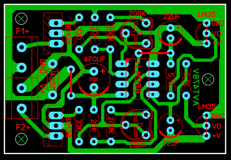
LM35 Fan PCB Design
Note: The PCB design was created using Sprint Layout 6, checked but not tested.
Setting the LM35 Temperature
Setting up the circuit is quite easy: Trimpots determine the temperature at which the fans start.
Heat the LM35 sensor to your desired temperature.
Adjust the temperature at which the fan starts by turning the trimpot.
Repeat the same process for the second fan channel.
This adjustment will keep your device exactly within your desired temperature range.
Circuit Test Video
About the LM35 Series Temperature Measuring Sensor

The LM35 series sensors have an output voltage that is linearly proportional to temperature (Celsius) (the output voltage of the LM34 varies according to Kelvin). The measurement range is from -55 to 150 °C. The linearity coefficient is +10.0 mV/°C, meaning that the output voltage increases by 10mV for every 1 degree Celsius increase. It has an accuracy that can correspond to 0.5 °C at room temperature and can operate between 4 and 30 volts. The measurement range also varies depending on the LM35 model. These ranges are given below:
LM35, LM35A -55°C to +150°C
LM35C, LM35CA -40°C to +110°C
LM35D 0°C to +100°C
can measure.
The voltage value for the desired temperature is found using the formula: Desired temperature (°C) x 10⁻¹ (mV / °C) = output voltage (mV).
Source: SCIENCE and TECHNOLOGY, July 2006, Hacer Erar
Circuit source: sklep.avt.pl/pl/products/regulator-obrotow-wentylatorow-w-komputerze-pc-zlutowany-kit-avt-478-165483.html


