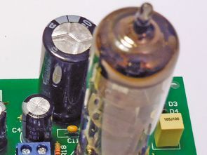
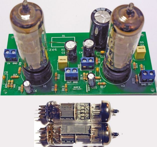
The lamp used in the project is PCL805 tube. Older Readers may remember it because it was used in the vertical deflection pattern of most tube TVs. Today it can be obtained for free or almost free because it has not found use in today’s acoustic amplifiers built by many enthusiasts.
What parameters does this lamp have? First of all, what can be read from the first letter of the symbol is an electric current lamp of 300 mA. On televisions, all filaments were connected in series and powered from the mains, eliminating the need for an expensive transformer. The approximate glow voltage should be read from the catalog note – typically it is approximately 17.5 V.
PCL805 Tube Preamplifier schematic diagram
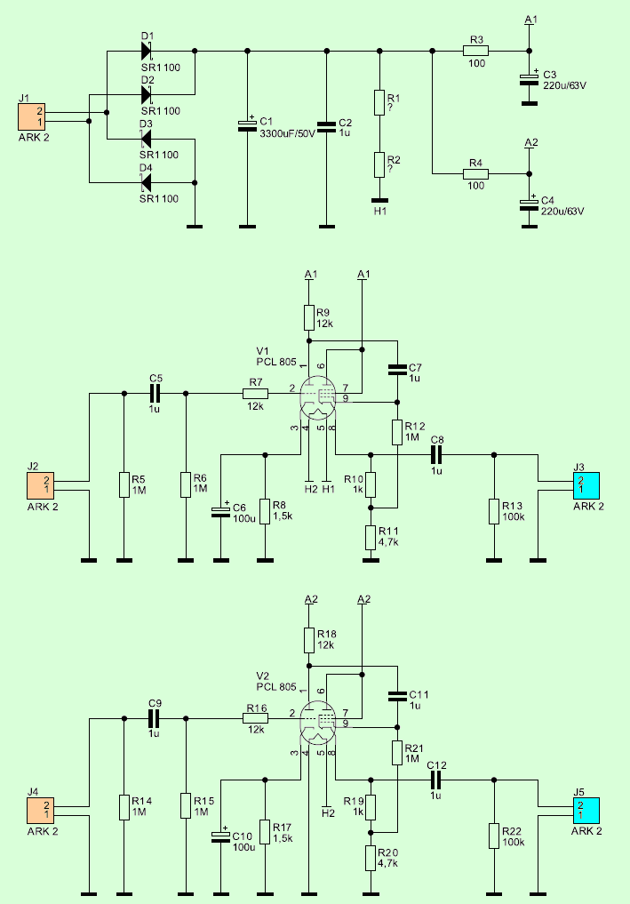
It is divided into three parts: the power supply and two identical channels. The power supply used in the project is very simple but sufficient. The sinusoidal voltage is straightened by the Graetz bridge made of Schottky D1 … D4 diodes. This is to reduce the voltage drop and to reduce the bridge power loss compared to conventional rectifier diodes. The pulsating voltage is filtered through capacitors C1 and C2, with the latter being shorted to high frequency interference mass.
Straightening and filtering out the voltage causes it to increase (in relation to the effective voltage) so that it can be used to power two filament lamps connected in series. Resistors R1 and R2 are used to determine the correct glow current, as described below. The same voltage is used to power the lamp electrodes. Therefore, before each channel there are additional filtering members, implemented as simple RC filters. They restrict crosstalking between channels and further filter the 100Hz ripple created by straightening the alternating voltage across the Graetz bridge.
![]()
FILE DOWNLOAD LINK LIST (in TXT format): LINKS-25848.zip


PCL805 Röhren-Niederspannungs-Stereo-Vorverstärker
Die Lampe im Projekt ist PCL805 Röhre. Ältere Leser erinnern sich vielleicht daran, weil sie im vertikalen Ablenkungsmuster der meisten Röhrenfernseher verwendet wurde. Heute kann es kostenlos oder fast kostenlos erhalten werden, da es in heutigen akustischen Verstärkern, die von vielen Enthusiasten gebaut wurden, nicht Verwendung gefunden hat.
Welche Parameter hat diese Lampe? Was aus dem ersten Buchstaben des Symbols gelesen werden kann, ist zunächst eine elektrische Stromlampe von 300 mA. Bei Fernsehern wurden alle Glühdrähte in Reihe geschaltet und vom Netz gespeist, wodurch ein teurer Transformator überflüssig wurde. Die ungefähre Glühspannung sollte aus der Katalognotiz abgelesen werden – typischerweise beträgt sie etwa 17,5 V.
PCL805 Röhrenvorverstärker-Schaltplan