The first block is built on the NE555, which acts as a free-wave generator. VR1 50k potentiometer and C1 capacitor and VR3 100k potentiometer and capacitor C2 are responsible for the “rotation” speed. The VR3 potentiometer at maximum resistance increases the rotation speed.
The rotation speed is in the range of 20 … 75 Hz. This value is approximate and is due to the tolerance of the capacitors. The rotation speed is reduced when we turn the VR3 100k potentiometer so that its resistance decreases to zero, then we get a rotation speed in the range of 0.02 … 3 Hz.
NE555 Siren circuit schematic
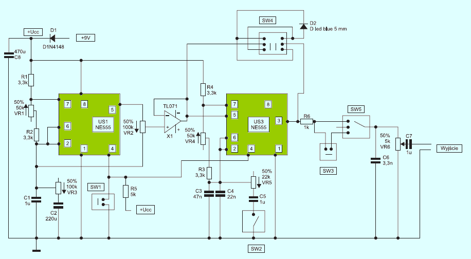
The NE555 oscillator frequency of the NE555 is in the range 110 … 2150 Hz. With the addition of a C5 capacitor to the combined capacities C3 and C4, the frequency range is 30 … 300 Hz. The frequency range adjustment is powered by the VR5 potentiometer. In addition, the SW2 rocker switch is connected in series with this potentiometer, which can be used to disconnect the VR5 22k potentiometer and the C5 capacitor.
NE555 has added a SW4 dual-ring switch to which the external pins connected to the cross have been soldered with the diode, and two center pins are connected to the voltage control input (pin5) and the output of the NE555 (pin3).
Adding a LED in the feedback loop causes the voltage to be summed as soon as the diode conductor voltage threshold is exceeded. This combination causes a stepping of the modulation voltage range, which allows for the original, “crazy” sound of our “siren”. In addition, the switch SW5 switches on behind the R6 resistor, which selects the type of siren sound.
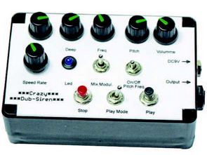
NE555 siren sample
![]()
FILE DOWNLOAD LINK LIST (in TXT format): LINKS-25872.zip


NE555 Super Sirenenkreislauf
Der erste Block baut auf dem NE555 auf, der als Freiwellengenerator fungiert. VR1 50k Potentiometer und C1 Kondensator und VR3 100k Potentiometer und Kondensator C2 sind verantwortlich für die “Dreh” -Geschwindigkeit. Das Potentiometer VR3 bei maximalem Widerstand erhöht die Drehzahl.
Die Drehzahl liegt im Bereich von 20 … 75 Hz. Dieser Wert ist ungefähr und beruht auf der Toleranz der Kondensatoren. Die Drehgeschwindigkeit wird reduziert, wenn wir das Potentiometer VR3 100k so drehen, dass sein Widerstand auf Null sinkt, dann erhalten wir eine Drehzahl im Bereich von 0,02 … 3 Hz.
NE555 Sirenenschaltplan