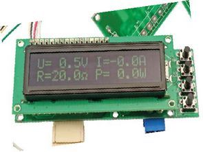
In addition to measuring voltage, current, power and temperature, the meter can also calculate the resistance of an attached load. However, this is not the most important difference – more importantly, this meter can also measure negative voltage and current. Recommendations: the meter can be used in a laboratory power supply or other power system.
The Atmega88 Multi meter circuit will be used primarily in laboratory power supplies, in which it is convenient to observe several electrical quantities at the same time. For example, how much current the attached device consumes depending on the value of the supply voltage.
Temperature measurement is also useful in this application. After a slight modification of the software, you can control the relay switching on e.g. the fan on the heat sink after exceeding the limit temperature. By changing the dividers at the meter inputs and calibrating the meter, you can change the measuring range.
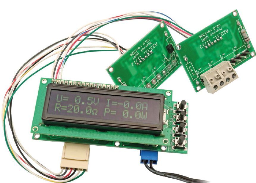
The meter consists of two, optionally three plates. On one there is a switch mode power supply, Atmega88 microcontroller, LCD display and keyboard, on the other voltage dividers and shunts for measuring current. This construction made it easier to conduct paths that conduct high currents.
In addition, the plate of dividers and shunts can be placed in a place distant from the Atmega88 microcontroller board, which facilitates the wiring of e.g. power supply, where the current part is usually located at the back of the housing, and the meter on the front panel.
The power supply was built using the MC34063A impulse stabilizer operating in a typical step-down configuration. As a reference voltage source for input voltage dividers, a 1.1 V built-in Atmega88 microcontroller filtered with a C5 capacitor was used. The operational amplifier U3 buffers the reference voltage and supplies it to the resistors R33 … R40, which together with the serial resistors on the input board form a voltage divider.
The 0 V voltage at the divider input corresponds to 0.55 V at the A / C converter input
Voltage -1.1 V – 0 V at the input of the A / C converter.
+1.1 V – +1.1 V voltage at the input of the A / C converter.
This makes it possible to measure negative voltage without using operational amplifiers at each input.
Schematic diagram of the Multi meter circuit
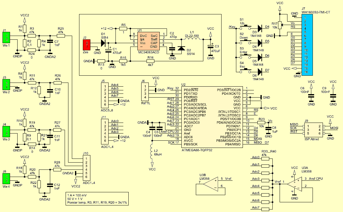
The 4-button keyboard for operating the meter menu is attached to the LCD display bus. So that pressing more than one button does not interfere with data transmission to the LCD, separating diodes D4 … D7 are used. The board dimensions have been adapted for a 2×16 character LCD display. It is enlarged in relation to the LCD by space for buttons.
The meter can use a 4 × 16 character display, so there is no need to switch screens (the results of all eight measurements are simultaneously visible on the LCD screen). If we use a 4×20 character display, the measurement results are more readable, especially in the range of negative temperature or higher than 99.9 °C or power greater than 99.9 W when presented from the left side of the display.
The display with a resolution of 4 lines of 20 characters is so wide that it covers the keyboard. Due to the fact that with such a display it is used only for the meter calibration function, the buttons can be mounted on the other side of the board. One might wonder whether for displays of 20 characters not display the second decimal place in the measurement results, but taking into account the accuracy of the transducer in the Atmega88 microcontroller, this does not seem expedient.
![]()
FILE DOWNLOAD LINK LIST (in TXT format): LINKS-26494a.zip


Mesure de tension, courant, température, puissance et résistance de charge
En plus de mesurer la tension, le courant, la puissance et la température, le compteur peut également calculer la résistance d’une charge attachée. Cependant, ce n’est pas la différence la plus importante – plus important encore, ce compteur peut également mesurer une tension et un courant négatifs. Recommandations: le compteur peut être utilisé dans une alimentation électrique de laboratoire ou tout autre système d’alimentation.
Le circuit multimètre Atmega88 sera principalement utilisé dans les alimentations de laboratoire, dans lesquelles il est pratique d’observer plusieurs grandeurs électriques en même temps. Par exemple, la quantité de courant consommée par l’appareil connecté en fonction de la valeur de la tension d’alimentation.
La mesure de la température est également utile dans cette application. Après une légère modification du logiciel, vous pouvez contrôler l’activation du relais par ex. le ventilateur sur le dissipateur de chaleur après avoir dépassé la température limite. En changeant les diviseurs aux entrées du compteur et en calibrant le compteur, vous pouvez changer la plage de mesure.