A more powerful and advanced automatic Battery desulfurizer circuit as an alternative to the “Battery Repair Desulfurator Circuit” project. The circuit is used to dissolve the sulfate on the battery plates. If you ask what the desulphator feature is, it is stronger than other circuits, has high, low voltage and overheating protection and can be used on a working system.
ATTENTION: During the desulphation process, the charger voltage must be between 13.6V and 13.8V, higher voltage may cause battery cells to fail. Also, the room temperature must not be too low (below 15°C) during desulphation.
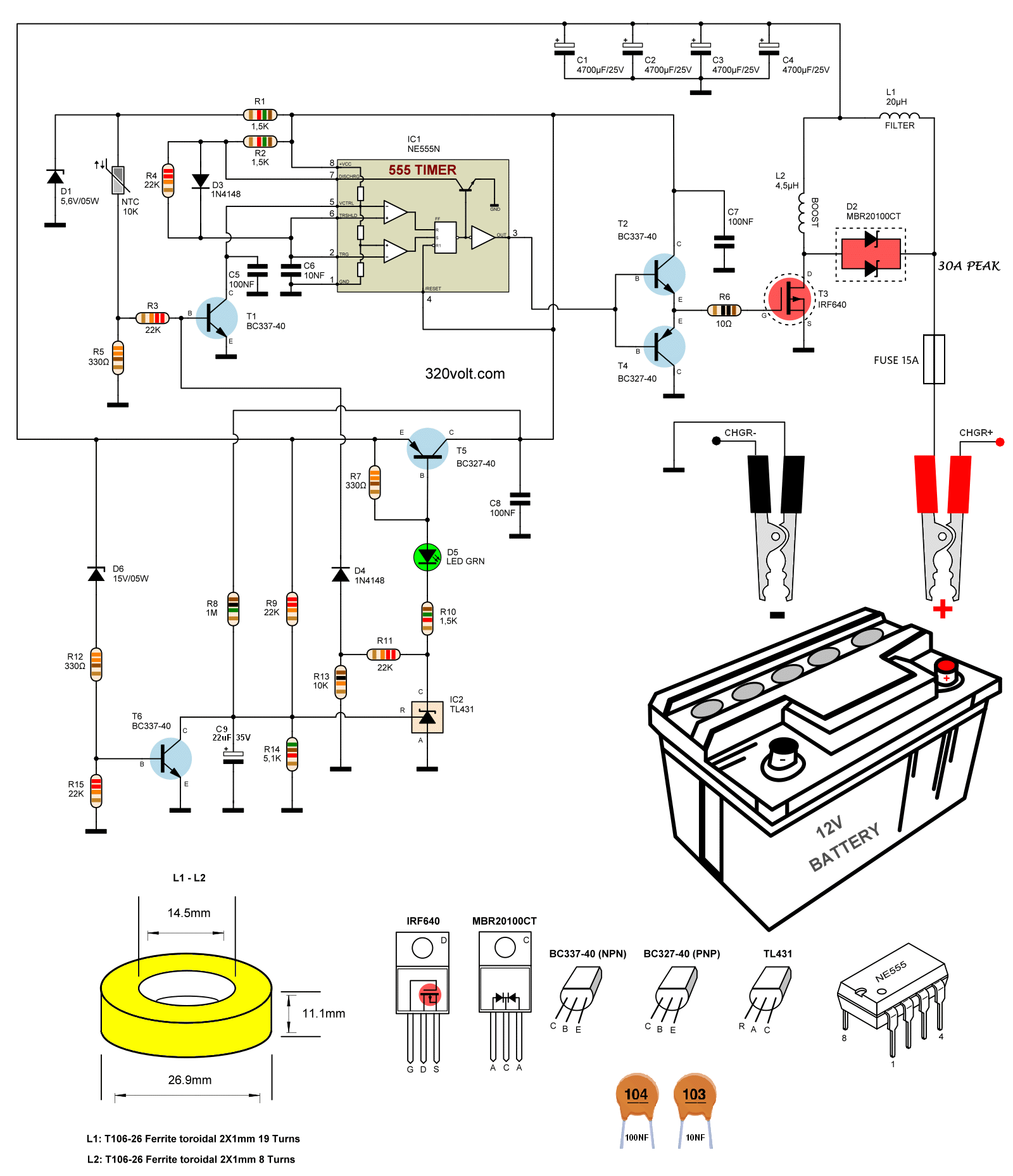
The 12V Desulphator device basically works as a pulsed voltage boost converter. The power part is controlled by the NE555 timer IC, which works as an astable flip-flop. The length of the pulse arriving at the gate of the IRF640 Mosfet transistor is determined by the R2 resistor and C6 capacitor.
The switching time of the IRF640 Mosfet Transistor is approximately 15 us with the power of the pulse used components. It loads the L2 coil with a current of approximately 30A. After the end of the pulse, this current is discharged to the battery through the D2 MBR20100 diode. The discharge time is set by a 22K R4 resistor and a 10NF C6 capacitor is about 150 us, which corresponds to a switching speed of about 6 kHz.
When the voltage begins to drop below 13.3V, the power (and also power consumption) decreases continuously, and at 13.0V the desulphator device is completely turned off. The circuit consumes 1.2mA at 12.6V. It is a well-thought-out feature to prevent battery drain in batteries connected to the solar energy system or in cars, that is, in systems that are not constantly charged, and the sulphate dissolving process is more effective above 13V.
As I mentioned in the other article, batteries that are in very bad condition; pure water, battery water, battery acid etc. Fluid supplements, known by different names, should be administered and studies should be carried out. The circuit is at full power, consuming about 8W of power when the voltage is above 13.3V.
The desulphator device also has overvoltage protection. The T6 BC337 transistor ensures that the circuit is turned off when the 15V Zener D6, 330-Ohm R12 and 22K R15 battery voltage exceeds 15.5V. The main reason for this protection is to protect the NE555 integrated circuit.
There is also protection for overheating. NTC thermistor with 10 kOhm resistance at 25°C is connected to the common cooler with T3 and D2. When the temperature exceeds approximately 50°C, the thermistor resistance will drop to approximately 3.3 kOhm. This causes transistor T1 BC337 to open and the width of the pulse produced by NE555 to decrease. The protection adjusts the power to maintain the temperature up to 55°C.
Battery Sulfur Cleaning Desulphator 12V Circuit Diagram
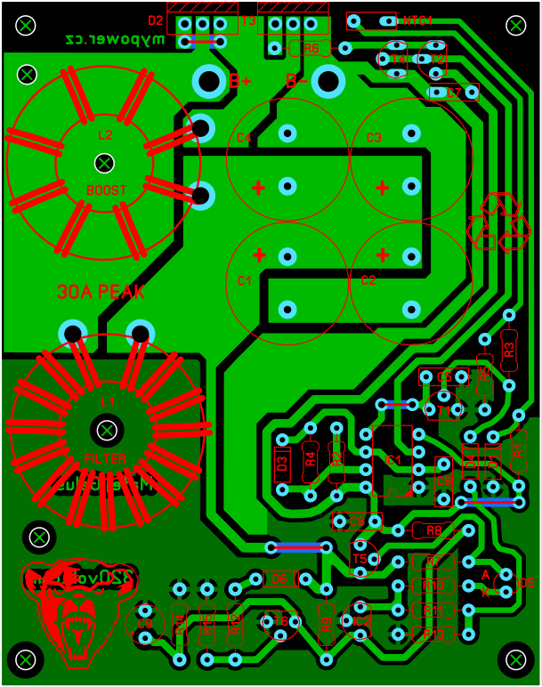
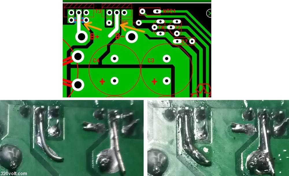
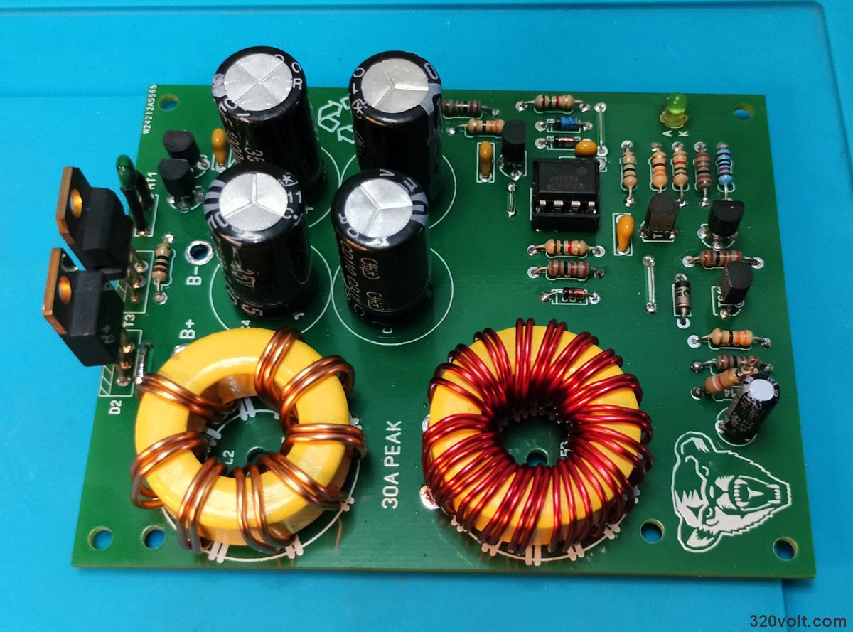
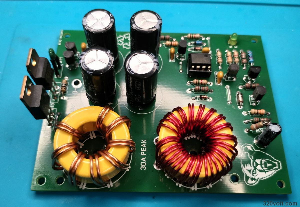
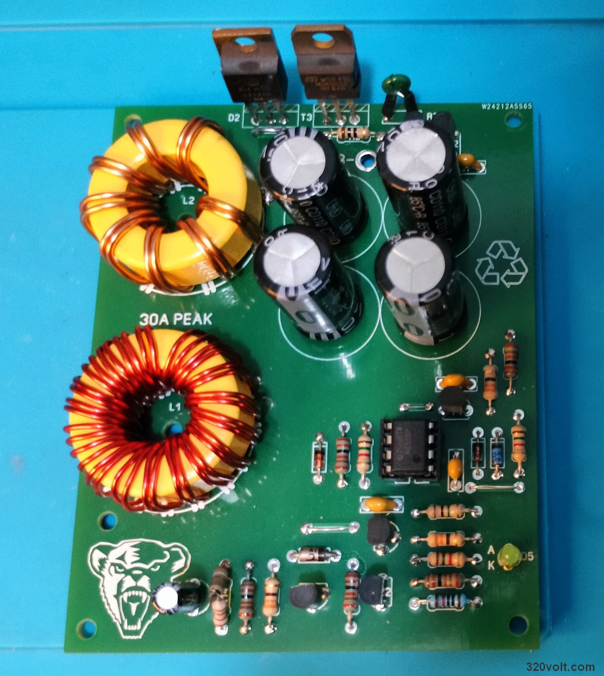
The PCB printed circuit drawing of the battery maintenance desulfurizer circuit was made with Sprint layout 6. The PCB is single-layer, dimensions are 77.7×98.7mm. It would be a good idea to strengthen it by soldering wires to the 2 sections shown in the picture below, or you can use a thick solder filling.
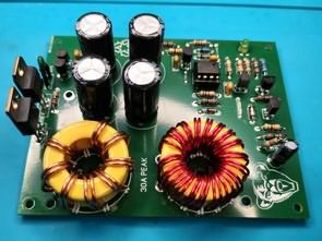
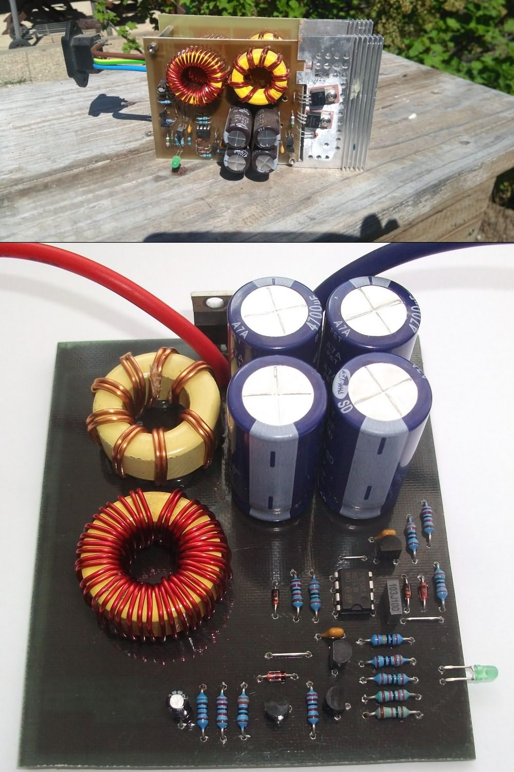
In the construction of the battery sulfur cleaning circuit, we have to wind our L1 and L2 coils ourselves. It is very difficult to find ready-made coils with high power at the desired values. I don’t like winding transformers and coils 🙂 but sometimes it is inevitable. If I can wrap it, everyone can wrap it 🙂 Actually, if I put in a little effort, I can get used to it and even it can be done with equipment that will make the job easier.
The ring cores used are T106-26 iron powder cores with an outer diameter of 27 mm. You can obtain these cores from new or old computer AT-ATX power supplies (output filter coil). You can also re-wrap the wires you removed from the cores. You can use the wire of the 12V winding (2 pieces) for the L1 coil and the wire of the 5V winding for the L2 coil.
Note: If you can find it, you can obtain the required values by decreasing the windings of coils with similar values and appropriate power. For example, you can remove the windings of 30uH coils for a 20uH coil and 10uH coils for a 4.5uH coil, make measurements and use them. Coil meter required for measurement.
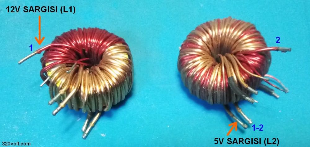
The L1 coil consists of 19 windings, and the L2 coil consists of 8 windings. The diameter of the wire for winding is min. 2x1mm . You can wind it with a single 2mm wire, but since it is harder, it makes winding a little difficult.
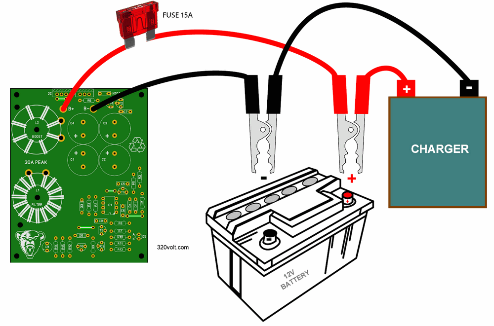
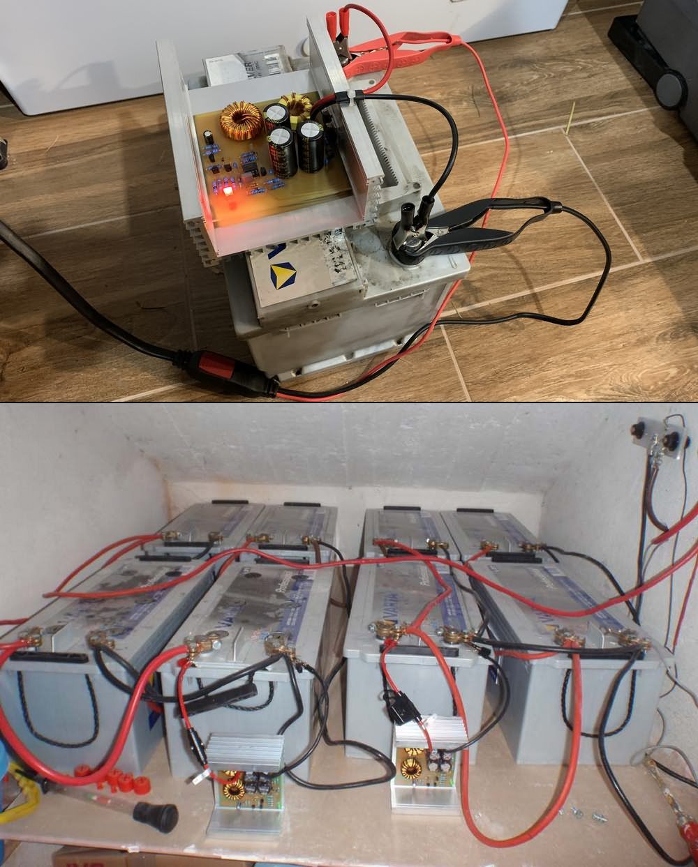
Connection of the circuit: Connect a 12V battery. The LED on the circuit gives a slightly weak light. Then increase the voltage on the battery above 13.3V using a charger or power supply. The LED will emit strong light and the circuit will start operating with an audible high tone at a frequency of 6 kHz. Do not operate the D2 MBR20100 and T3 IRF640 without a heatsink for more than a few seconds as there is a risk of these elements overheating! Don’t forget to insulate the cooler connection. It is necessary to ensure good contact between the NTC Thermistor and the heatsink. A small amount of thermal paste will be applied between the NTC Thermistor and the cooler. The maximum thermal resistance of the cooler should be 5°C/W, the optimum is around 3°C/W.
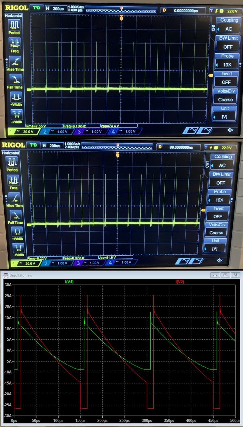
In short, the circuit will be noisy, the coils, MOSFET and diode will get hot… The current pulse in the circuit is so fast that it is difficult to measure even with an oscilloscope. Voltage ranges from 60 to 100V, these values vary depending on the battery’s power, performance and charging voltage. You can see voltage pulses with an oscilloscope.
Finally, the circuit was made and approved by many people. Some users even use batteries connected to active solar panels. Even though the circuit is actively designed to suit a system (for example, a car), I find it healthier to separate the battery from the system and perform the desulfation process, all kinds of protection measures have been taken, but I am a bit of a guarantor 🙂
Source: wiki.mypower.cz/desulfator


Dear There,
Is-it possible to buy the pcb?
Hope tohear from you.
Best Regards.
Habib Bhiri
Hi,
https://www.pcbway.com/project/shareproject/Pulse_De_sulfator_for_Lead_Acid_Battery_Resurrection_7c1920de.html
You can buy it in only PCB or PCB+Assembly
Hello, nice schematic -based on the original- BUT yours doesn’t work !
The 30Amp labelled diode, does al the effect done !
You should use two batteries, or one adjustable PSU to feed energy,
preferably above 15Volts .
And the Battery “to desulphate” should go in series with the diode,
with its (+) terminal on the Cathode, and (-) to the +Vcc 15Volts or even more.
And do not use a Shottkey, they have too big invers leakage current.
Take a Fast rectifier from an SMPS to scavenge off.
Best regards, Harry
Hello, nice schematic -based on the original- BUT yours doesn’t work !
Please don’t feel yet insulted, but see this as a ways to help 😉
The 30 Amp labelled diode, kills al the -EMK effect !
So renders it useless !
You should use two batteries, or one adjustable PSU to feed energy,
preferably above >15Volts .
And the Battery “to Désulphate” should go in series with the diode,
with its (+) terminal on the Cathode, and (-) to the +Vcc >= 15Volts or even more.
And do not use a Shottkey, they have too big invers leakage current (mAmps).
Take a Fast rectifier from an SMPS to scavenge off.
Best regards, Harry.
Thanks for the feedback. But Works very well in practice. No problems.
https://ibb.co/Lz2v6cNs
Hi is possible to order