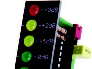
LM3916 Vu meter Circuit Indicator rna 10-point reading field made of LEDs. The diodes were scaled in dB, transmitting irn, from D4 to D13, respectively, the following weights: -20 dB, -10 dB, -7 dB, -5 dB, -3 dB, -1 dB, 0 dB, +1 dB, +2 dB, +3 dB.
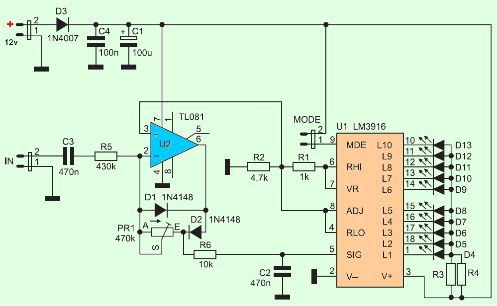
The LED indicator may work in line or spot mode. It is selected by placing the MODE jumper. If she is compact, the meter works in line mode. If open, in point mode. The input signal is led to the In input through
C3 capacitor and R5 resistor. Then it is fed to the peak detector input made of D1 and D2 diodes, PR1 potentiometer and U2 operational amplifier. Using potentiometer PR1 you can adjust the amplitude of the output voltage sciowego. Detector input resistance it’s big, so it doesn’t overload the signal source too much.
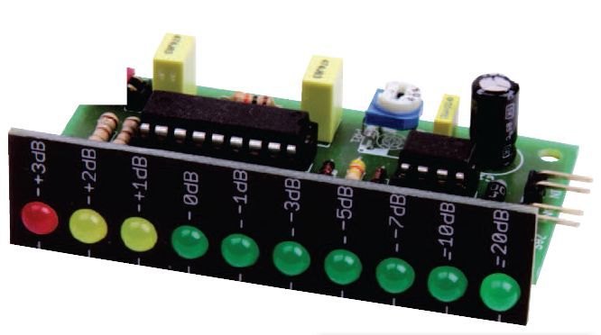
The assembly diagram is shown in Figure 2. After assembly, the only required regulatory action
is the calibration of the detector. The 0 dB level is assumed to be 0.775 V (0 dBu). In order to
calibration should be at the input of constant voltage 1.1 V (more precisely: 1.096V), and then
set the PR1 potentiometer LED D13 (+3 dB) is on. There are source LM3916 vumeter pcb drawings prepared with Eagle cad (board and LED Panel)
LM3916 Vu meter Circuit Schematic Diagram
![]()
FILE DOWNLOAD LINK LIST (in TXT format): LINKS-26539b.zip


20 dB Vu mètre Circuit LM3916
LM3916 Vu mètre Circuit Indicateur rna Champ de lecture à 10 points composé de LED. Les diodes ont été mises à l’échelle en dB, transmettant irn, de D4 à D13, respectivement, les poids suivants: -20 dB, -10 dB, -7 dB, -5 dB, -3 dB, -1 dB, 0 dB, +1 dB, +2 dB, +3 dB.
L’indicateur LED peut fonctionner en mode ligne ou spot. Il est sélectionné en plaçant le cavalier MODE. Si elle est compacte, le compteur fonctionne en mode ligne. Si ouvert, en mode point. Le signal d’entrée est dirigé vers l’entrée In via
Condensateur C3 et résistance R5. Il est ensuite envoyé à l’entrée du détecteur de crête composée de diodes D1 et D2, d’un potentiomètre PR1 et d’un amplificateur opérationnel U2. À l’aide du potentiomètre PR1, vous pouvez régler l’amplitude du scénario de la tension de sortie. La résistance d’entrée du détecteur est grande, donc elle ne surcharge pas trop la source du signal.