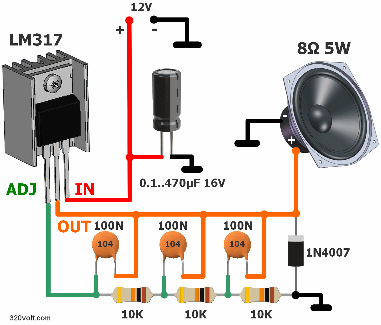
A simple electronic siren circuit using the adjustable regulator integrated LM317T. Sound is produced with a 384 Hz square wave that oscillates approximately 9.8 Volts peak-to-peak. The RMS power of the siren is around 2W. It is recommended to use 8-OHM 5W speakers.
The siren contains a power generator and a repeater that converts the electrical signal from the generator into sound. In the generator, LM317T integrated with TO220 case adjustable positive output voltage is used. It is completed with the RC circuit from C1 to C3 and R1 to R3 and oscillates as a multivibrator at a frequency of 384 Hz. The oscillation time is approximately 2.6 ms.
The LM317T output has a rectangular signal at high levels with voltage H of 9.8 Volts and duration of 0.8 ms and at low levels of voltage L of 0 Volts and duration of 1.8 ms. To achieve the loudest possible sound, the speaker must be placed in a suitable cabinet.
In order for the multivibrator to work properly, it must be loaded with a speaker or an 8.2 0./5 W resistor.
A protective diode (01) is connected to the output terminals, which suppresses the voltage peaks induced in the oscillating coil of the speaker when the current flowing through this coil is turned off.
Briefly, the function of the multivibrator acts as a comparator with the LM317T’s power input IN, output OUT, and non-inverting input ADJ.
The external DC voltage applied to the ADJ input is compared with the voltage at the internal inverting input of the comparator; this is an internal reference voltage that is 1.25 Volts lower than the voltage at the output OUT.
When a voltage greater than the voltage at the internal inverting input is applied to the ADJ input, the voltage at the OUT output increases, resulting in a voltage difference of 1.25 Volts between the OUT and ADJ pins.
Due to the positive feedback provided by the RC cell, simultaneously with the increase in the voltage at the OUT output, the voltage at the ADJ input increases even faster. Therefore, the voltage at the OUT output is
When the saturation voltage of the OUT output is approximately 2.2 Volts less than the supply voltage applied to the IN input, it rises steeply until positive saturation.
When saturation is reached, there is a voltage difference of approximately 1 Volt between the OUT and ADJ terminals, so the LM317 remains in saturation. However, it charges from C1 to C3 and R1 to R3, so the voltage at the ADJ input gradually drops.
When the voltage difference between the OUT and ADJ terminals exceeds 1.25 Volts, approximately 0.8 ms after saturation, the voltage at the OUT output begins to decrease to maintain the 1.25 Volt voltage difference between the OUT and ADJ terminals.
Due to the positive feedback provided by the RC cell, simultaneously with the decrease of the voltage at the output OUT, the voltage at the ADJ input decreases even faster. Therefore, the voltage at the output OUT quickly drops to zero.
When the voltage at the OUT output drops to zero (relative to ground), there is a voltage difference of about 1.5V between the OUT and ADJ terminals, so the LM317T remains in this state. But C1 to C3 discharges from R1 to R3, so the voltage at the ADJ input gradually increases.