
In power electronics, an active DC rectifier module using MOSFETs increases efficiency and minimizes losses. MOSFET rectifiers can advantageously replace both classic silicon diode and bridge rectifiers, as well as bidirectional, symmetrical rectifiers.
Its biggest advantage is achieving minimum power losses (ten times smaller than diodes). This results in high efficiency, low heat loss, minimal cooling requirements, increased reliability, energy savings, and cost savings.
Active MOSFET Rectifier
Contents
In devices with higher current consumption, such as various stabilizers, whether linear or switched-mode power supplies, chargers, or power amplifiers, one of the main causes of power losses is the DC rectifier used to operate the device.
In the case of an efficient switched-mode power supply fed by a line transformer or Class D amplifiers, this can reach a point where the DC rectifier losses exceed the sum of other losses in a highly efficient device (and this doubles for low-voltage rectifiers with high current consumption).
We had a switching power supply with over 95% efficiency that barely warmed up at 5A, and also an excellent bridge rectifier that would normally require an amplifier several times larger than a 300W Class D amplifier, so it was time to do something about it.
To reduce losses at higher currents in the power rectifier, it’s possible to replace the existing silicon diodes with Schottky diodes that have a lower voltage in the same direction at the same current without additional modifications.
Unfortunately, this difference is only at its highest at low currents and is no longer so noticeable at higher currents, but the savings are visible.
It also depends on the type used, but Schottky diodes with the lowest forward voltage at high currents are only manufactured with voltages as low as 60 volts and are made for currents up to 20A.
However, if we want to achieve minimum losses that will eliminate the need for heatsink/heatsink, we need to look for a slightly more complex solution: using a MOSFET as an actively controlled rectifier.
To understand how significant the difference in loss reduction is between a MOSFET and a traditional silicon or Schottky diode, look at the graph in Figure 1 (970mV and 9.7W power loss), then the same is true for the MBR4060 Schottky diode (450mV forward voltage drop and 4.5W power loss), and finally for the IRF3205 MOSFET type transistor (D.S. junction voltage drop of only 70mV and power loss of only 0.7W), the IRF3205 is more than 2 times cheaper than the MBR4060 Schottky diode.
DC Rectifier Losses

Active DC Rectifier Circuit Diagrams


80 Plus Certification
I see rectifier systems using MOSFETs instead of diodes in new generation PFC-supported computer power supplies. However, they still use diodes in the high-power, i.e., 12V, line. Anyway…
In 2003, an organization was established to promote higher efficiency in power supplies used in computing and multimedia technologies. Based on tests conducted by the 80 Plus organization, certifications are awarded to power supplies with efficiency higher than 80%.
Various versions of the certificates are available. Certification of resources based on efficiency;
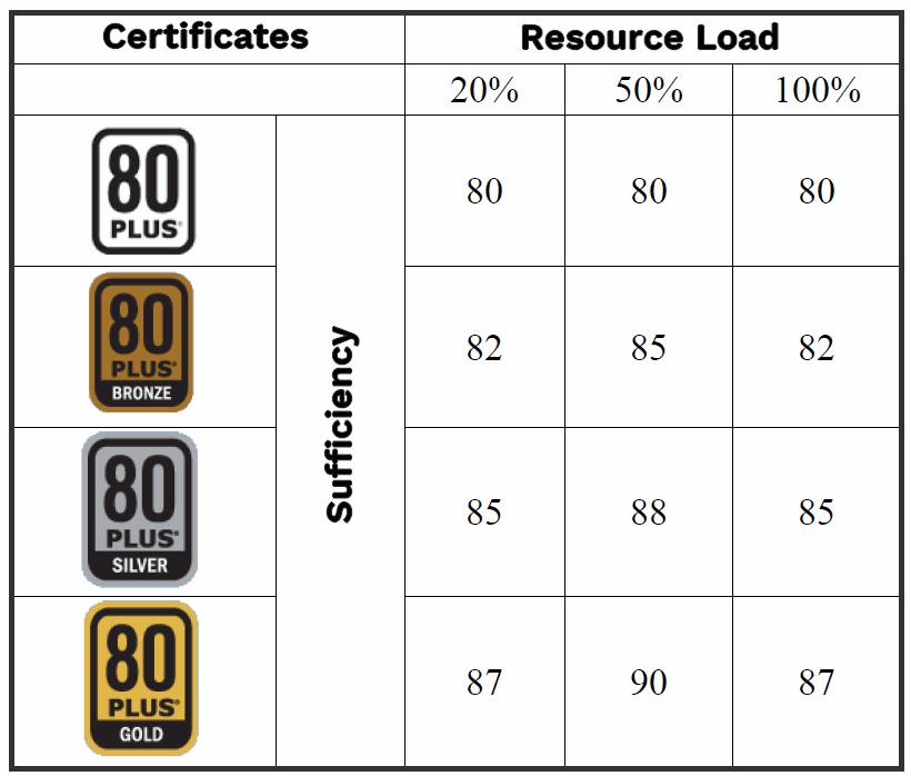
The power supplies were tested for either 115V ±1% or 230V ±1% input voltage. Power supplies with higher input voltages will have higher efficiency due to lower input current. Measurements are performed for different loads of 20%, 50%, and 100%.
Minimum efficiency limits are set for each load; these limits must not be exceeded, otherwise the power supply’s efficiency will not reach the specified certification.
80 PLUS Certification
Another requirement for obtaining 80 PLUS certification and above is a power factor of cosP 0.9. The advantage of using such certified power supplies is primarily savings in operating costs, lower heat generation and consequently higher reliability, lower cooling requirements, and lower noise.
Ultimately, it is necessary to evaluate whether the aforementioned advantages outweigh the high price. Power supply selection is also important. It is preferable that the power supply and the device’s power consumption are similar. The disadvantage of 80 PLUS certifications is that they don’t consider the power consumption in standby mode. In this case, power consumption can reach up to 10W.
ATX Power Supply MOSFET Rectifier Circuit Diagram
I’ve created a diagram of a new generation ATX power supply MOSFET rectifier, sold in the market with price tags between 750…850W; it’s an interesting design.

This article, prepared by Karel Barton, has been used as a source by many in their theses. I am also attaching these to the file. The 0-30V 0-5A power supply made with LM317 & LM741 uses IR2101 and IRF3205 MOSFETs in the DC rectifier stage.
The other application is a 20V 5A SMPS circuit. NCP1230 and NCP4302 are used, and the rectifier MOSFET is IRFS4010.
Source: forosdeelectronica.com/threads/rectificaci%C3%B3n-activa-con-mosfet.165761/


