Sound card adapter Multiple devices can be connected to the audio signal output of a computer sound card at the same time: a tower, a TV set, a speaker set, etc. Each of these devices loads the output to some extent and it may happen that the signal attenuation is too strong. This circuit is designed to reduce the output impedance of the sound card, without introducing audible distortion. It is designed to work with stereo systems.
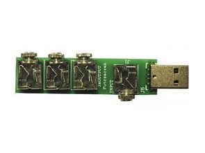
The spindle can be powered from a USB connector, of which there are usually several in a PC. It has four stereo 3.5 mm jack sockets: one input, which is used to input the signal from the card, and three output, connected in parallel. The plate is designed in such a way that it can be embedded in a heat shrink tube.
The operational amplifiers included in the MCP602 system play the role of voltage repeaters. They are supplied with 5 V unbalanced voltage and therefore it is necessary to increase the potential at the non-inverting input to approx. 2.5V. This voltage produces a divider consisting of resistors R8 and R9. The C5 capacitor, together with the internal resistance of this divider, creates a filter that blocks interference that could get into the inputs.
Schematic diagram MCP602 Sound card adapter
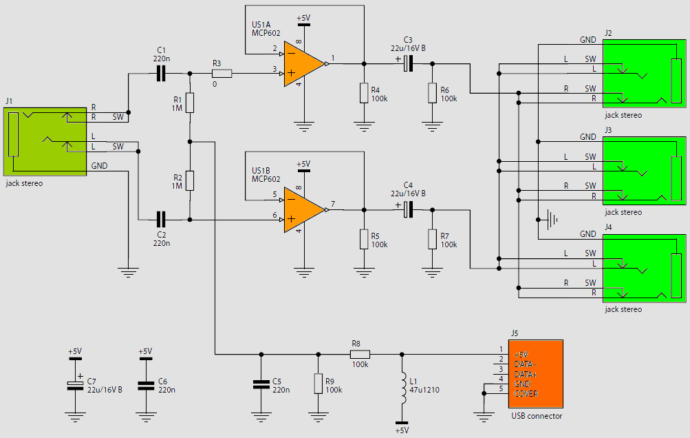
Non-inverting inputs are polarized through R-1 1mohm and R-2 1mohm resistors, which set the input impedance to 1MV. Capacitors C1 220nf and C2 220nf cut off the constant component. There is no need to add resistors to compensate for the input currents, because they are very small, on the order of picoamps.
The output signal is taken via C3 and C4 capacitors with a relatively large capacity (22mF), which makes it possible to transfer low frequencies. Resistors R4 and R5 are designed to linearize the output stage of the operational amplifier by ensuring a continuous current flow from the output. Resistors R6 and R7 maintain the potential of negative covers at zero and – after turning off the system – discharge the output capacitors.
The L1 choke and capacitors C6, C7 filter the voltage supplying the system. This is especially necessary when powering the system from a computer in which digital circuits generate interference on power lines. The values of the elements have been selected so that the entire acoustic spectrum (20Hz … 20kHz) is transferred. This requirement will be met for the resultant load impedance greater than approx. 400 V.
The system is assembled on a single-sided printed circuit board with dimensions of 18 mm × 70 mm, the assembly diagram of which is shown in Figure 2. After proper assembly with checked elements, the follower does not require any startup operations and is immediately ready for operation.
The USB connector is only used to power the system, so the voltage source can be another device, such as an amplifier or a separate power supply. When operating the system, make sure that the peak-to-peak value of the input signal does not exceed approx. 3.5 V, because this may cause the effect of “latching” amplifiers, which results in unpleasant distortions.
For typical sound cards, providing an output amplitude of about 1.5 V (3 Vpp), this effect should not occur. Three output sockets are mounted on the board, connected in parallel. If their number turns out to be too small, additional signal splitters can be used.
![]()
FILE DOWNLOAD LINK LIST (in TXT format): LINKS-26340.zip


Adaptateur de carte son MCP602
Adaptateur de carte son Plusieurs appareils peuvent être connectés à la sortie du signal audio d’une carte son d’ordinateur en même temps: une tour, un téléviseur, un haut-parleur, etc. Chacun de ces appareils charge la sortie dans une certaine mesure et cela peut arriver que l’atténuation du signal est trop forte. Ce circuit est conçu pour réduire l’impédance de sortie de la carte son, sans introduire de distorsion audible. Il est conçu pour fonctionner avec des systèmes stéréo.
La broche peut être alimentée à partir d’un connecteur USB, dont il existe généralement plusieurs dans un PC. Il dispose de quatre prises jack 3,5 mm stéréo: une entrée, qui est utilisée pour entrer le signal de la carte, et trois sorties, connectées en parallèle. La plaque est conçue de manière à pouvoir être intégrée dans un tube thermorétractable.
Les amplificateurs opérationnels inclus dans le système MCP602 jouent le rôle de répéteurs de tension. Ils sont alimentés en tension 5 V asymétrique et il est donc nécessaire d’augmenter le potentiel à l’entrée non inverseuse à env. 2.5V. Cette tension produit un diviseur composé des résistances R8 et R9. Le condensateur C5, associé à la résistance interne de ce diviseur, crée un filtre qui bloque les interférences qui pourraient pénétrer dans les entrées.
Diagramme schématique Adaptateur de carte son MCP602