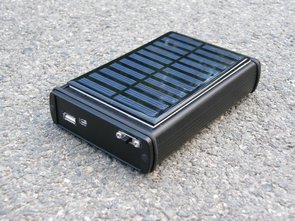
The solar cell powered back-up power supply should be as efficient as possible, it should be simple construction due to possible failures and should be reasonable sizes. The design of the charging inverter was based on the recommended connection available from LTC3536 drive datasheet, operating at 1.8 – 5.5 V input voltage I used the free LT spice IV simulation software, which is free to download on the Linear Technology website.
It was necessary to provide the circuit for soft power supply (large series resistance) feedback. This feedback is meant to monitor the voltage of the solar cell, and that in it meaning that as soon as the voltage falls below a specified limit, the feedback comparator increases the voltage on the FB pin, reducing the inverter output voltage. Tension on this pin it is 0.6 V in normal operation to a non-inverting OZ input reference voltage of 2.5 V. For this purpose I used reference diode LM366. The voltage divider R8, R9 is set to give feedback reacted when the UIN dropped below 3.5 V. Shotky’s diode D2 was designed to disconnect the branch feedback at the time of its inaction.
Solar Cell Backup USB Power Supply Circuit Schematic
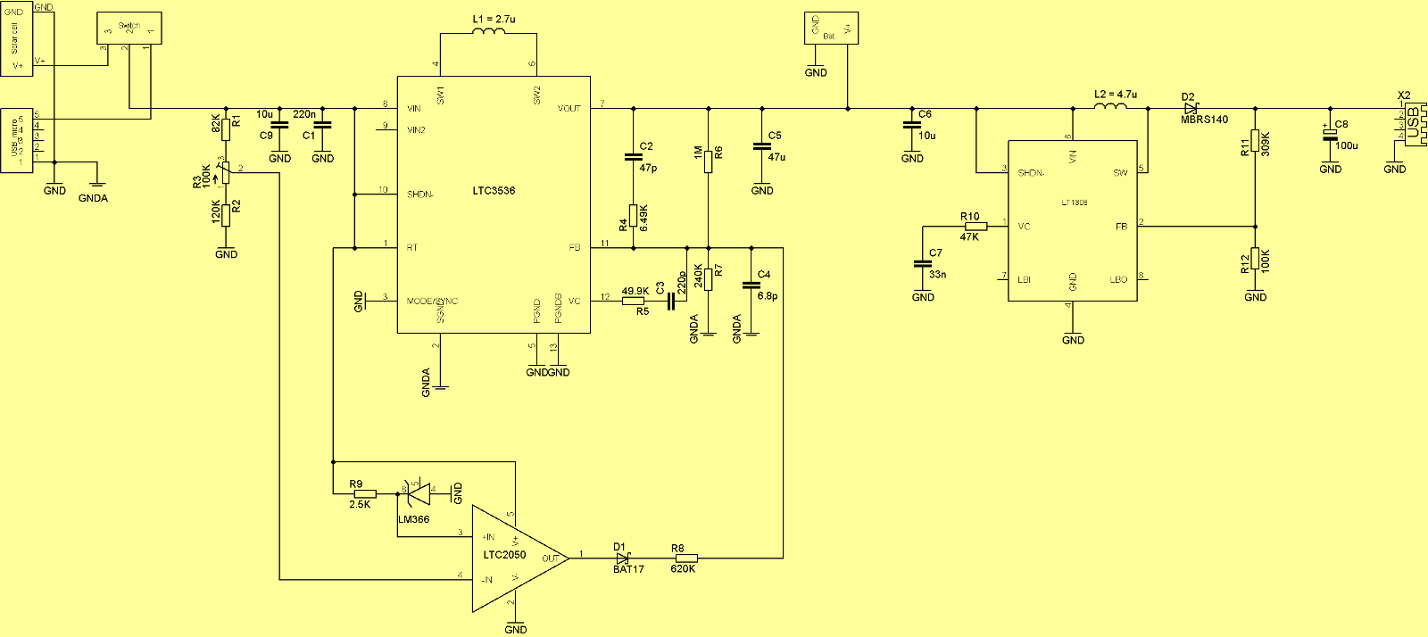
But when we increase this voltage artificially, the inverter evaluates the situation as higher
the output voltage and the output voltage starts to decrease. Thereby the power is taken by the circuit and the input voltage begins to increase. The circuit can operate in PWM or Burst mode, which is set by wiring pin named MODE / SYNC. According to the following graph, we can determine dependence efficiency depending on mode and current consumption. I chose PWM mode due to its lower current limit.
For this purpose I chose the Linear Technology LT1308IS8 boost converter. It has the advantage of automatically switching from PWM mode to Burst mode, which has higher efficiency with less current draw. It is designed for output voltage of 5 V and maximum power of 1 A. With normal PWM mode, the minimum output voltage ripple is declared. used in mobile stations, camcorders, pagers, cordless phones, and battery back-up sources. Switching frequency of 600 kHz allows connection with small ones SMD components. It is supplied in an osmipine SO package.
![]()
FILE DOWNLOAD LINK LIST (in TXT format): LINKS-26120.zip


20W Stereo Amplifier With TDA2003 Tone Control
20W Stereo Amplifier With TDA2003 Tone Control
Many times we have been asked about an amplifier that can be powered with the computer source to amplify this. We have also seen the need for an amplifier that can be transportable everywhere and that provides an acceptable power service. Thinking about filling these expectations, we present a 20W stereo amplifier (10W per channel) with 3-way tone control, included in the same printed circuit.
This amplifier uses the integrated circuit TDA2003 that has the same configuration and distribution of the pins of the TDA2002. The interesting thing about this integrated is that it uses very few external components, its assembly is very simple, low cost and uses little space. The TDA2003 provides an output current of up to 3.5 A, very low harmonic or cross-over distortion. It has protection against short circuit of DC and AC, thermal protection over the allowed range, dump of the load voltage peaks of up to 40V and accidental earth breaks. In conclusion it is a good option when it comes to an amplifier for the work table or the room. Ideal for beginners, although we must clarify that any circuit, however simple, sometimes has its drawbacks
TDA2003 Amplifier Schematic
LT1308IS8 LTC3536 Circuit d’alimentation USB de secours pour cellule solaire
L’alimentation de secours alimentée par cellule solaire doit être aussi efficace que possible, sa construction doit être simple en raison d’éventuelles pannes et ses dimensions doivent être raisonnables. La conception de l’onduleur de charge était basée sur la connexion recommandée disponible dans la fiche technique du variateur LTC3536, fonctionnant à une tension d’entrée de 1,8 à 5,5 V.
Il était nécessaire de fournir le circuit pour une rétroaction d’alimentation douce (résistance de grande série). Cette rétroaction est destinée à surveiller la tension de la cellule solaire, et cela signifie que dès que la tension tombe en dessous d’une limite spécifiée, le comparateur de rétroaction augmente la tension sur la broche FB, réduisant la tension de sortie de l’onduleur. La tension sur cette broche est de 0,6 V en fonctionnement normal à une tension de référence d’entrée OZ non inverseuse de 2,5 V. Pour cela, j’ai utilisé la diode de référence LM366. Le diviseur de tension R8, R9 est réglé pour donner une rétroaction réagissant lorsque l’UIN est tombé en dessous de 3,5 V. La diode D2 de Shotky a été conçue pour déconnecter la rétroaction de la branche au moment de son inaction.
Schéma du circuit d’alimentation USB de sauvegarde des cellules solaires