Modification of the LM723 2N3055 stabilized power supply. I have always been concerned that the voltage drop is large when a load is applied and this is clearly visible even with a 30V voltmeter. (After adjusting the voltage with no load, 100 to 200mV drops when 3 to 4A load is applied)
In particular, when charging an external battery made for the PB2400c (10,800 mAh with 6P4S configuration of lithium-ion cells), the charging current drops significantly due to the voltage drop long before the voltage reaches the upper limit (approximately 16.8 V). (Although the resistance of the cable and connector from the power supply to the cell seems to be about half the cause)
Looking at the voltage loss of each part when the load is applied with the digital multimeter, the voltage has decreased in the following parts. Characteristics of the stabilized power supply circuit of the PS-0141 kit used. There are also points such as the resistance of the board pattern (the place where the current passes is quite thin) and the configuration that can be reduced to 0V with the LM723 (I could not understand the mechanism because I am an amateur). Even if I look at the circuit diagram this part may be related.
Resistance due to wire material and length used. There seems to be about 10mV loss per 10cm at 3.5A even though wire materials such as cheap speaker cables are used.
The contact resistance of the switch installed on the output terminal side on the + side. A small 125V AC 6A switch (new) is used, but the loss changes slightly each time the switch is turned on, and at 3.5A at best there seems to be about 1.5 to 2 mV loss.
When used with a large load, the temperature in the case rises significantly due to the heat of the power transistor, transformer and concrete resistor for current detection, so the voltage fluctuation over time is large.
Using the LM723, I tested it with the basic circuit configuration written in the LM723 spec sheet and found that the stability of the LM723 with respect to load is pretty high with a voltage drop of about 3 to 4 mV at 17V 3A.
Therefore, the stabilization circuit has been changed to the following circuit configuration. A 0.2 mm thick x 6 mm wide copper plate is used for the + side (thick line in the schematic) and – side (thin line in the schematic) of the circuit.


LM723 Power Supply Schematic

To reduce the effect of wire resistance, connect the output voltage detector and the – side of the board as close as possible to the output terminal as shown in the circuit diagram above. Also, the wire (about 6 cm) from the + side switch to the output terminal doubles, resulting in a loss of 2.5 to 3 mV at 3.5 A.
For the loss of the switch on the output side, it may be better to replace it with a switch for a slightly larger current or connect two or more switches in parallel, but like this time.
The connection between the Johnson terminal and the wire was screwed in by soldering the wire to a 0.2mm thick copper plate, but the loss on the – side was a bit large, so I redid it. After reinstallation, the loss of the connector is approximately 1.2 mV at 3.5 A for both the + and – side.
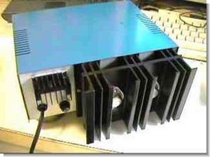
For heat dissipation, a φ60mm 12V 0.14A fan is installed at the bottom of the case and the board is placed vertically on this fan. In addition to the heat dissipation of the circuit and transformer, the heat sink also has a heat dissipation effect because there is a hole in the heat sink side. As a result, it is seen that the voltage fluctuation stabilizes over time with an increase of 4-5mV in 30 minutes with a 20V 3.5A load. For the fan’s power supply, parts of the kit that use another LM338 are placed on a small board and power is supplied by turning on the AC side switch.
The capacitor of the smoothing circuit of the main power supply has been changed from 6800uF + 2700uF + 2200uF = 11700uF to 6800uF + 4700uF = 11500uF due to backlash.
Recently, the rotary switch used to select the transformer’s output had poor contact (the weak current switch was unreasonable), so I replaced it with a more durable switch that I purchased separately. I skipped 1 step and changed it to 3 steps as 12V, 18V and 24V since the current 2 lines x 6 steps but not a short type type.
By making a variable resistor for the current limit as shown in the circuit diagram above, the output current can be set to almost zero and only a stone resistor with a small resistance value is required for current detection.
After the improvement, the voltage drop was reduced to about 13mV when a 3.5A load was applied (when the output side switch loss was lowest) with the voltage set to 20V at no load. I also connected the voltmeter as close to the output terminal as possible, but the voltmeter is at such a level that the voltage change due to the presence or absence of a load cannot be detected.
By changing the peripheral circuit of the LM723, the voltage adjustment range changed from 0 (about 60mV actually) to 21.5V, from 2.6 to 25V. With a load of less than 6Ω, there will be no surge up to about 23V 4A (less than 10uV, the measurement limit of a digital multimeter), but if the voltage is increased beyond that, a 100Hz surge will occur due to full-wave rectification.
Source: asahi-net.or.jp/


LM317 Li-Ion Batteries Fast Charger Circuit
Lithium-ion rechargeable battery, charging in a constant voltage constant current system. Charger No-load voltage is a deep discharge battery check if below 2.9V per cell 0.1ltmA after charging at a certain time than 3.0V per cell stop Check voltage imbalance in every cell battery voltage, if abnormal voltage stop One is a single cell voltage of 4.2V or 4.1V or more when the stop