Light Activated Switch Circuit. Switches, including those reacting to changes in lighting, are still very popular and practically used by electronics or automation specialists. This time we propose to make a simple light-responsive switch system, but powered directly from 230 V AC.
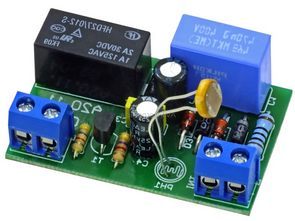
while the assembly diagram in Figure 2. The actuator that powers the light bulb is a relay with contact load up to 1 A.
The system is powered from a 230 VAC network via a transformerless power supply containing a R1 resistor, C1 … C3 capacitors and D1 1N4007 … D4 1,3W/12V ZENER diodes. The C1 470NF capacitor limits the current that the device can draw from the power network, and the R1 resistor protects the D1 … D4 diodes against damage due to overload that would occur when it was connected to the network. The rectifier bridge consists of D1 … D4 diodes in a Graetz system.
D3 and D4 diodes are Zener diodes, which simultaneously limit the supply voltage to about 12 V. The rectified voltage is filtered by C2 220UF 16V and C3 100NF capacitors. When the intensity of light falling on the PH1 photoresistor decreases, its resistance increases. As a consequence, the T1 BC516 transistor is turned on and the PK1 relay closes the contacts by connecting the network voltage to the CON2 connector.
Schematic Diagram Relay Switch Circuit
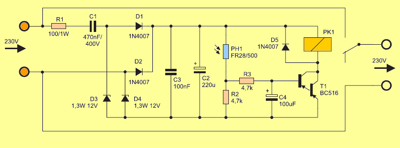
The C4 100UF 16V capacitor protects the system against brief changes in lighting. It allows to eliminate the possibility of oscillations when the level of lighting is on the border of the system activation. Photoresistor resistance in daylight is several hundred Ω, and after dark it increases to several dozen k-ohm.
The switch activation threshold has been set permanently, but you can always correct it by choosing the value of resistor R2 4.7k-ohm. When starting the switch, extreme caution should be exercised because the system is powered directly from the power grid.
![]()
Caution the circuit operates with high voltage be careful of capacitor connections + – if you connect the poles upside down there may be large explosions at high voltage the insured power line before running the circuit,use protective goggles
FILE DOWNLOAD LINK LIST (in TXT format): LINKS-26258.zip


Interrupteur à relais activé par la lumière (alimentation sans transformateur)
Circuit de commutation activé par la lumière. Les interrupteurs, y compris ceux qui réagissent aux changements d’éclairage, sont toujours très populaires et pratiquement utilisés par les spécialistes de l’électronique ou de l’automatisation. Cette fois, nous proposons de créer un système de commutation sensible à la lumière, mais alimenté directement à partir de 230 V AC.
tandis que le schéma d’assemblage de la figure 2. L’actionneur qui alimente l’ampoule est un relais avec une charge de contact jusqu’à 1 A.
Le système est alimenté à partir d’un réseau 230 VAC via une alimentation sans transformateur contenant une résistance R1, des condensateurs C1… C3 et des diodes ZENER D1 1N4007… D4 1,3W / 12V. Le condensateur C1 470NF limite le courant que l’appareil peut tirer du réseau électrique, et la résistance R1 protège les diodes D1… D4 contre les dommages dus à une surcharge qui se produirait lors de sa connexion au réseau. Le pont redresseur est constitué de diodes D1… D4 dans un système Graetz.
Les diodes D3 et D4 sont des diodes Zener, qui limitent simultanément la tension d’alimentation à environ 12 V. La tension redressée est filtrée par des condensateurs C2 220UF 16V et C3 100NF. Lorsque l’intensité de la lumière tombant sur la photorésistance PH1 diminue, sa résistance augmente. En conséquence, le transistor T1 BC516 est passant et le relais PK1 ferme les contacts en connectant la tension du réseau au connecteur CON2.
Schéma du circuit du commutateur de relais