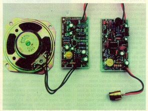
Laser Communication Circuit We can provide wireless audio communication with the laser communication circuit described below. In fact, if a parabolic reflector is used, this distance can easily be a few kilometers, and even at this distance the sound transmission will be very clear. Lazy receiver and transmitter circuits. At 5 miliWat power, we used a kind of laser diode that emits a beam of 650 nm wavelength, which we use in our laser pointers.
The receiving circuit and the transmitting circuit are fed separately with a 9 volt battery. The emitter circuit collects electret microphone sounds and emits a laser diode. The receiver uses a 4-36 ohm speaker and contains an amplifier. To operate the system, the laser receiver and transmitter must be able to see each other as usual. It is very difficult to intervene and listen to someone else in this system. Also, an infrared (IR) laser diode can be used if desired, and no one can see the beam.
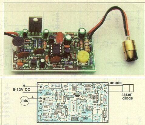
Laser Sound Transmitter Schematic
Lazerin akımı VR1 ile ayarlanır.
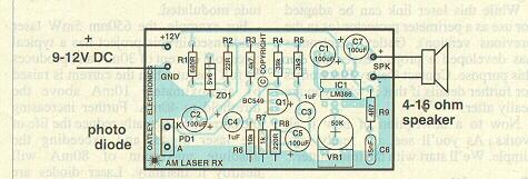
Laser Receiver Circuit Diagram
Laser sound Transmitter Description: The operating value of the laser diode (5mW 650 NM) is typically 30mA. The laser is operated between 1-40mA. The laser diode current decays when it exceeds 80mA. The metal sheath is removed as it will cause damage in excess temperature. The circuit uses 68 ohm NTC for temperature protection. In this way, the working life of the laser diode is 20.00 hours.
Parts Placement Plan of the Transmitter and Transmitter of the Transmitter. The red LED used in the transmitter is vibrating harmoniously when the sound signals are received.
Receiver Description: The signal sent by the transmitter is received by the photodiode in the receiver. The visible light should be a photodiode that is used in this circuit. The receiver uses the LM386 amplifier. It is driven by a speaker with a small resistance of four ohms and pulling 350 mW of 9 volts from the coil.
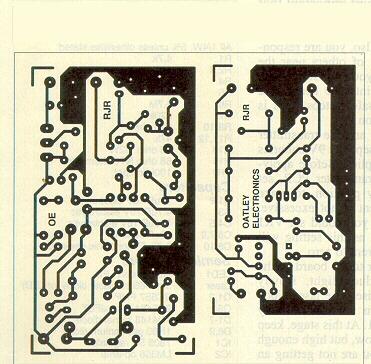
Placement Plan
The photodiode is mounted directly on the receiver plate. Carefully solder the laser diode because it may deteriorate from excessive heat. It can be done by taking cooling measures.
First open the transmitter and bring VR1 to the half position. Turn it clockwise. Slowly turn it clockwise to increase the current and see the light of the laser diode. You also need to flicker on the LED when you click on the microphone. Here the laser beam does not shake.
The receiver and transmitter are placed at a distance of 1 meter. When the receiver is turned on, the loudness of the loudspeaker is visible, and if necessary, a piece of paper can be placed in front of the photodiode to prevent excessive noise. This paper should not be used in normal use because the distance will increase. In this way the output of the microphone is controlled by the speaker output.
Laser Sound PCB
Material List
Rl 4.7k
R2,3 1 00k
R4 68k
R5 10k
R6 4.7M
R7 220k
R8-1 0 220 ohm
Rl 1,12 47k
R13 56 ohm 1/2W
R14 68 ohm NTC thermistör
VR1 1 00k trimpot
Cl,2 1OuF 16V
C3 4.7uF 16V electrolytic
C4,5 10OuF 16V electrolytic
C6,7,9 68nF
C8,1 0 0.47uF bipolar
Semiconductors
LED1 5mm yeşil LED
Lazer 5mW/65Onm laser diode
Ql,2 BC557 PNP
03 2N5484 N-ch JFET
Dl-7 1N4148 signal diode
D8,9 1 N60 germanyum diode
lci 7805 5V reg.
1C2 LM358 op-amp
PCB 65mm x 36mm
8-pin IC socket; 9V battery and battery clip.
Receiving List
Rl 680 ohm
R2 22 ohm
R3 4.7k
R4 39k
R5 3.gk
R6 10k
R7 1 k
R8 220 ohm
Rg 4.7 ohm
VR1 50k trimpot
Cl,2,5,7 10OuF 16V electrolytic
C3,4 1 uF 16V electrolytic
C6 15nF poly.
Qi BC549 NPN
LM386
ZD1 5.6V 40OmW zenner
PCB 36mm x 64m
Foto diode
9V pil
speaker
8 pin soc
source: derinelektronik.com


Laser-Tonübertragungsschaltung
Laser-Kommunikationsschaltung Wir können eine drahtlose Audiokommunikation mit der unten beschriebenen Laser-Kommunikationsschaltung bereitstellen. Wenn ein Parabolreflektor verwendet wird, kann dieser Abstand in der Tat einige Kilometer betragen, und selbst in dieser Entfernung ist die Schallübertragung sehr klar.
Lazy Empfänger und Sender Schaltungen. Bei einer Leistung von 5 Milliwatt verwendeten wir eine Art Laserdiode, die einen Strahl von 650 nm Wellenlänge emittiert, den wir in unseren Laserpointern verwenden.
Die Empfangsschaltung und die Sendeschaltung werden getrennt mit einer 9-Volt-Batterie gespeist. Die Emitterschaltung sammelt Elektretmikrofongeräusche und emittiert eine Laserdiode. Der Empfänger verwendet einen 4-36 Ohm Lautsprecher und enthält einen Verstärker. Um das System zu betreiben, müssen Laserempfänger und -sender sich wie gewohnt sehen können. Es ist sehr schwierig zu intervenieren und auf jemand anderen in diesem System zu hören. Wenn gewünscht, kann auch eine Infrarot (IR) -Laserdiode verwendet werden, und niemand kann den Strahl sehen.
RC Tone Control Circuit Calculator
RC Tone Control Circuit Calculator
Simple Passive RC Tone Control Circuits and Simple Tone Control Circuitry bass treble rc filter sharing circuits in the source program I have just recently realized that I have been archived in the past .. Fender, Vox, Marshall, James, E series, Bench, Big Muff, Hiwatt The passive tone control circuits can see the operating frequencies, responses better than standard schemes on resistances, capacitors, potants. You can change the values. You can see how the tone control circuit works with different values. To change the element value, you need to double click on it with maus and enter the new value.
Passive Tone Control Calculation Program
Circuit de transmission du son laser
Circuit de communication laser Nous pouvons fournir une communication audio sans fil avec le circuit de communication laser décrit ci-dessous. En effet, si un réflecteur parabolique est utilisé, cette distance peut facilement être de quelques kilomètres, et même à cette distance la transmission du son sera très nette. Circuits émetteurs et récepteurs paresseux. À une puissance de 5 miliWat, nous avons utilisé une sorte de diode laser qui émet un faisceau de 650 nm de longueur d’onde, que nous utilisons dans nos pointeurs laser.
Le circuit de réception et le circuit d’émission sont alimentés séparément avec une batterie de 9 volts. Le circuit émetteur recueille les sons de microphone à électret et émet une diode laser. Le récepteur utilise un haut-parleur de 4-36 ohms et contient un amplificateur. Pour faire fonctionner le système, le récepteur et l’émetteur laser doivent pouvoir se voir comme d’habitude. Il est très difficile d’intervenir et d’écouter quelqu’un d’autre dans ce système. En outre, une diode laser infrarouge (IR) peut être utilisée si vous le souhaitez, et personne ne peut voir le faisceau.