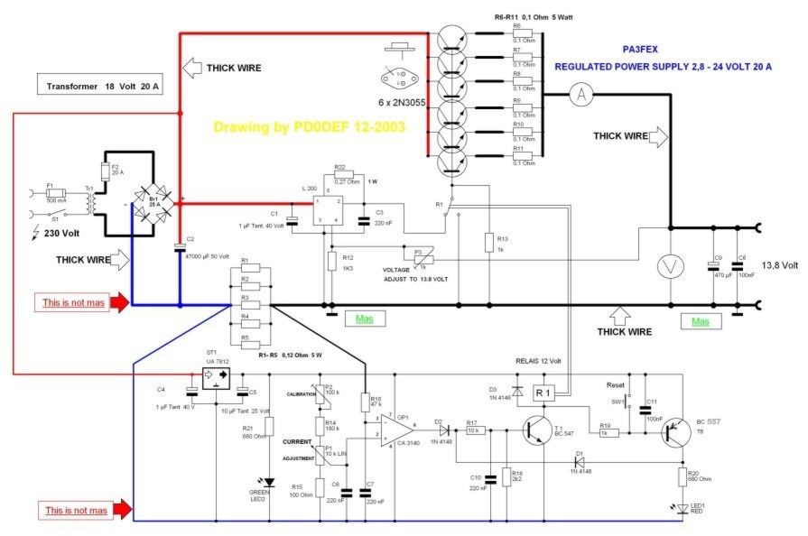
The circuit is based on the adjustable voltage current regulator IC. With 6 2n3005, the output power of the IC can be adjusted with the increased output voltage. 13.8 volts is determined for 20 amps.
The circuit has current protection, it switches to protection when there is overcurrent or short circuit. Since it is high power, the relay used protection circuit based on the ca3140 opamp, calibration with 100k potentiometer, current limit can be adjusted with 10k potentiometer, also there is a pcb file prepared with sprint laout
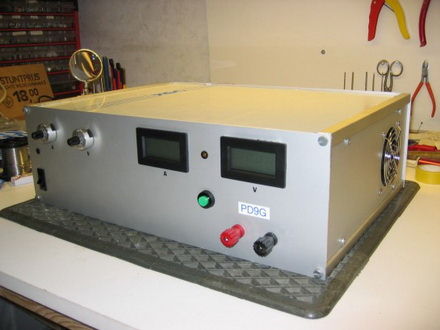
This Power Supply has been successfully recreated by various amateur friends. To be clear: the power supply can also be adjusted for more or less power. The regulation of the voltage is done by an L200. The power supply is also equipped with a current limiter that turns off the power supply if there is too much current.
In this case, no current will continue to flow, unlike many conventional power supplies. Conventional power supplies often have controls that fold back some of the power. If you want to have a current range of 2 -20 A for a conventional control, then for 2 A there should be a base-emitter voltage of 0.7 V across a resistor. This means that the resistance against which the current is measured should be 0.35 ohms.
U = I x R = 2 x 0.35 = 0.7 V.
The power dissipated in the resistor is then
P= L x I = 0.7 x 2 = 1.4 Watts
Now you will say that there is no mistake, but now we will look at the issue in 20A. The same R is still present here, now the voltage dropped to this:
U = I x R = 20 x 0.35 = 7V
The power dissipated is now
P = L x l = 7 x 20 = 140 Watts?
This looks very different and that’s why I edited it differently. It regulates in mVs. A certain reference voltage is applied to the 2nd leg of the CA3140, when the voltage at the 3rd leg is higher than the 2nd leg, the opamp will reverse and the protection will be activated. As a result, the power supply is de-energized and can then be restarted by pressing the reset button.
The measured resistance is 0.024 ohms, so 2 A = 48 mV and 20 A = 480 mV.
The dissipated power is now 0.096 and 9.6 Watts, respectively.
This also means that the Ri of the power supply is significantly smaller, with conventional regulation 7 volts should be set at 20 A, with this power supply only 0.48V.
At the defined power supply, the minimum limit can be set as: approx. 200 mA. 100k trimpot can be used for calibration. Position l: 10k potentiometer. 2 A. Position 2: 4 A. etc.
Normally this trimpot should be set to 60K, for 10 Amp power supply the potentiometer can be replaced with 5k type and the trimpot can be set to 65K. 3 x 2N3055 with 6 x 2N3055 right. All these data assume that the maximum current should be supplied at 12V or higher.
For a heavier power supply, the transformer, bridge cell and power supply capacitor will need to be adjusted and the number of power transistors will need to be increased. The measured resistors allow a current of 30A. The dissipated power is 21.6 Watts. The 180K resistor should therefore be changed to 100K, after which the potentiometer is adjusted to about 57K. Position 1 of the 10k potentiometer =3A, position 2=6A.
The rule of thumb for the size of the power supply capacitor is: 2000uF per amp. for 10A. is this 20,000uF; 30 A. For 60,000 uF, make sure that the negative wire from the bridge cell to the electrolytic capacitor and the voltage does not come into contact with ground or the case, otherwise the limitation will not work. The negative cable can be placed on the chassis at the output busbar, the enclosure should preferably be a metal box to prevent HF irradiation. Also make sure that the heat sink has adequate dimensions, with a 30 A power supply 300 – 400 Watts are easily converted into heat, of course the chosen transformer voltage plays a major role in this.
Also some tips on all types of feeding, when using a power supply for only 13.8 V, it is better to choose an 18 V transformer instead of 24 V. As a result, the power transistors heat up much less, beware, stabilization will also drop above 18 V. (depending on the desired power). This places higher demands on the cooling material used. B.V. It is better to use 4 power transistors than 2 very thick transistors, although 2 on paper will work, there will be much more heat development at the construction site.
It remains to wish you good luck with any restructuring.
L200 Power Supply Circuit


This device has been used by several fellow amateurs successfully reconstructed. For clarity, the diet is also to adjust for more or less power. The control of the voltage on the account taken of an L-200. The power supply is equipped with a current limit, which when too much current the power switch off. There remains no current flows, this is different than in many conventional power supplies. Conventional power supplies have arrangements that often what power “stoke” (foldback). If one wants a conventional arrangement of a power range from 2 -20 A, then there must be for all 2 A 0.7 V drop across a resistor, the base-emitter voltage. This means that the resistance which the current is measured to be 0.35 ohm, since
source pe5jw.nl/ L200 Adjustable Power Supply Schematic PCB alternative link


Atmega8 Experiment Development Board
In the folowing page I will present you an open source development board for ATMEGA8 builded especialy for Linux users. This development board is perfect for all the newbies that want to learn about AVR Microcontrollers or want to build some nice projects with it.
ATMEGA8 DevBRD contains:
*ISP programer
*RS232 comunication (serial port)
*HIGH POWER VOLTAGE control
*ON/OFF circuit
*All pins are marked
*PC power jack