Cnc project prepared motor control circuit basic elements L6203 and L297. H-bridge for stepper motors Very good 4 amp/phase driver for stepper motors. I’ve been dealing with CNC (numerical control machines) for a year and after various experiences I created this H bridge for stepper motors that can drive up to 4 amps pure bipolar type (4 wires) or 5.7 motors.
For motors configured in bipolar series (6 – 8 wires) The minimum current that can be delivered is approximately 500 mA and with this current range the bridge meets all piloting needs of amateur and industrial CNCs.
A year ago I purchased an H bridge kit for motors up to 2 amps/phase and it gave me some experience driving stepper motors. I even made a whole working cnc. I knew I had bridges suitable for driving small cncs and now it was time to move on to something more powerful and functional.
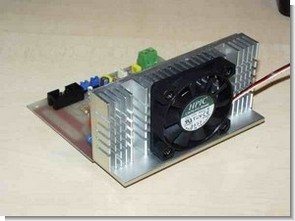
And here is the bridge I presented on this page. It uses two L6203 integrated circuits, each driving one phase, and an L297 that takes care of pitch conversion and implements the chopper. (a special engine driving technique designed to take better advantage of torque characteristics)
Electrical diagram of the H-bridge (470 microfarad electrolytic capacitor in the practical drawing is not available) Please note: 10 ohm and 1 ohm resistors must be of the 2 watt anti-inductive type.
I have used metal film resistors and many tradesmen know them as flame resistors. NEVER use wire resistors for this bridge (white ceramic ones or even wrapped wires very similar to the ones I use).
Stepper Motors Driver Project
Contents


On the base of the bridge is a trimmer and next to it a measure called Vref. The trimmer is used to adjust the voltage reference comparator of L297 and accordingly adjust the current flowing in the phases of the engine. To adjust the tension of course need a multimeter connected between mass and a measure Vref with a screwdriver and adjust the trimmer on the basis that you want to get on the engine. Note that the resistance of sense of this bridge with a total resistance of 0.33 ohms.
So the value of Vref derived directly from the bridge current supplied by the simple application of the law of ohms.
L6203 Dmos Full Bridge Driver

- supply voltage up to 48v
- 5a max peak current (2a max. for l6201)
- total rms current up to
- l6201: 1a; l6202: 1.5a; l6203/l6201ps: 4a
- rds (on) 0.3 Ω (typical value at 25 °c)
- cross conduction protection
- ttl compatible drive
- operating frequency up to 100 khz
- thermal shutdown
- internal logic supply
- high efficiency
L297 Stepper Motor Controllers

- normal-wave drive
- half/full step modes
- clockwise/anticlockwise direction
- switchmode load current regulation
- programmable load current
- few external components
- reset input & home output
- enable input
Source: fisertek.it L6203 L297 H-Bridge Stepper Motors Driver Circuit schmeatic pcb files alternative link:


Aluminum Soldering Method
First seen during the apprenticeship period, the repair of my masters at a different soldering technique on a two-piece aluminum grease thoroughly with a soldering iron back and forth as excavations made by continuous solder soldering soldering of aluminum have kept going after some effort
Hi
Password for 4808
Hi,
pass. 320volt.com