Infrared (IR) Receiver-Transmitter Project In this article, infrared (IR) transceiver circuitry will tell. The objective of making the circuits perform on-off remote device.
The circuit operation briefly as follows;
The first press of the button on the transmitter circuit, infrared LED light sends 38 kHz. This eye catching light in the receiver circuit by-pass relay transmission. Press the button again when the transmitter circuit, the relay contacts and messages out of my leaves.

Infrared IR transceiver Circuit
Contents
Counter integrated circuit 4017 is used. When it first opened in 4017 integrated receiver circuit tip number 3 (Q0) of transmission and the red LED light attached to this end. Means that the red LED is lit, it means that the relay is in transmission. Relay switch to conduction at the transmitter button is pressed, the receiver reviewing 4017 integrated 14 numbered leg (CLOCK) is signaled and integrated the No. 3 legs (Q0) messages out of my and the 2 nd leg (Q1) transmission passes.
As it is now the end of Q1 this end is connected to the transmission switches to relay messages and the green LED is lit. Green LED is lit, it means that the relay is in transmission. 4017 has integrated the outlet end of the 10 end but we no.4 (Q2) 15 The RESET tied to the end that we count with an integrated 3 and 2 makes the tip. To produce the 38 kHz infrared light transmitter circuit in circuit with 1K potentiometer adjustments are made.
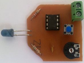
Transmitter circuit diagram of a bottom and a top view;


Receiver circuit diagram of a bottom and a top view;


I prepared with the circuit DipTrace program application files:
Note: Binary 0 in the receiver circuit the terminals of the circuit used for the input supply voltage. Triple the number 1 terminal is connected to the relay output.


White Led Bulb Modification
Previously, “Night Lamp with White Led, 20 pcs economical lamp with white LEDs project and 220volt with 19 pcs white LED energy saving lamp practices were shared’ll talk about saving bulb on the application made by removing the original parts.