The recent aquisition of a pair of vintage Infinity RS-5b speakers prompted a search for an amplifier to drive them. According to the documentation that came with my speakers, an amplifier between 35W and 135W is recommended (not my 10W at 10% THD piece of garbage Sharp 3-in-1). Initially, I looked at commercial amplifiers (Yamaha, NAD, and Rotel), but was disappointed at their fairly pedestrian distortion figures. Thus a new hobby project was born 🙂
I came up with some nominal specifications:
Stereo. Whilst I’ll use it for watching movies, my flat just doesn’t have the room for a full set of surround sound speakers. My main motivation is listening to stereo music sources, so a stereo amplifier is appropriate. Low THD and IMD. In audio-speak, this translates either as clinical or as accurate. I’m an engineer by trade, so prefer terms like THD over “warm” or “cold” which could mean anything. Given that most of the commercial amps offer 0.02% THD or thereabouts, I figured a good target was 0.001%. This means the harmonics and intermods will be 100 dB below the fundamental, and will thus mean that the system performance will be dictated by the source (CD) material, rather than the amplifier.
Ample power. 100W seems a reasonable amount. I currently live in a two bedroom flat, and don’t want my neighbours to kill me 🙂 However seriously, I figured 100W gives me a clear 20dB headroom at a nominal listening level of 1W.
Low noise. I usually listen to my music at reasonably low level, so it’s important for the amplifier input to have a low noise contribution.
Moderate cost. I’m happy to blow around $1000, as long as I get plenty of enjoyable hobby hours (and listening hours) as payback.
Good looks. This thing will (along with my preamp) live in my loungeroom. That means it needs to fit in. I don’t want something that looks like an escapee from my shed, so a significant part of the design is involved with building a nice case. Useability. This pertains more to the preamp, but I wanted the whole thing to be completely remote controllable.
Design Background
When I was a kid, one of my favorite monthly reads was ETI magazine. In January 1981, they published a series of articles describing the ETI477 MOSFET power amplifier, designed by David Tilbrook. This monoblock formed the basis of the “series 5000” HiFi amp. I desperately wanted to build one, but being all of 9 at the time, it wasn’t going to happen.
The neat thing about the series 5000 is that it was built around new (at the time) Hitachi lateral power MOSFETs. Most power MOSFETs (VMOS, trenchFETs, HexFETs etc) use a vertical structure, where the current flows vertically. This has the advantage of stunningly low Rds and hence high efficiency, but does nothing for linearity or capacitance.
Lateral MOSFETs are a much simpler structure, where the gate oxide is formed on a flat substrate, and the current flows across the substrate. This results in well defined, controllable device parameters, good linearity, and relatively low gate capacitance. However, the Rds of lateral MOSFETs is nothing to write home about.
Most amplifiers at the time (and now as well) used bipolar output drivers. Bipolar transistors are cheap and plentiful. They have relatively high transconductance, and can operate reasonably fast. However they have some drawbacks when used at high power. The main one is thermal runaway. The gain of a bipolar transistor increases as it gets hotter. That means that if there’s any imbalance between output transistors, the hottest one will pass most of the current, getting hotter until it ultimately expires. MOSFETs don’t have this problem. Their gain decreases with temperature, so they share the load well.
MOSFETs also have a high input impedance at low frequencies, and are capable (when driven by a suitable source) of extremely high slew-rates. Of course this very attribute makes them rather prone to HF oscillation when improperly compensated, but with careful design they’re capable of impressive intermod performance.
So having decided that now was the time to build a MOSFET amp, I wandered into the library at work and dug out the old ETI series 5000 amp articles, and had a read. I subsequently found that the series 5000 wasn’t Tilbrook’s final word on MOSFET amps. In 1987 he revisited the topic for a new magazine, Australian Electronics Monthly. This time (with the AEM6000 amplifier) he went all-out, with a matched-JFET differential input stage, and a complementary symmetrical voltage amplifier stage. A quest for super low distortion figures, with heaps of available gain. This looks like a good place to start.
Optimisation
There were a couple of drawbacks with the design. Firstly, it was based on obsolete TO-3 packaged lateral MOSFETs, and secondly the PCBs (like many kitset boards) were a pretty poor design anyway. I set to work redesigning the PCBs around modern flatpack equivalents (Hitachi 2SK1058 and 2SJ162). While I was at it, I swapped many of the remaining transistors for modern (faster) equivalents.
I made the following active device substitutions:
JFET input diffamp: SST404 (SO-8). Was ECG461.
Low power bipolars: MMBTA06/56 (SOT-23). Were BC547/557 and BC639/640.
Medium power bipolars: MJE340/350 (TO-126). Unchanged.
Power MOSFET drivers: 2SK1058/2SJ162 (TO-3P). Were 2SK176/2SJ56 (AEM6000) or 2SK134/2SJ49 (AEM6005 and ETI5000).
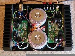
In order to dissipate 100W in an 8 Ohm speaker, one needs to put 28V RMS across the load. That’s 40V peak. At the peak (assuming a resistive load) the amplifier needs supply 5A. Doing the SOA sums (more later) means that 2 pairs of drivers are needed. Further, the Vgs for the MOSFET can be around 10V at high current. This means the supply must be at least 10V greater than the peak output voltage. A twin 40V transformer is appropriate, with a peak secondary voltage of +/-56V.
Now that I’d changed the transistors, I had to play with the values of most of the other components as well, in order to get reasonable performance while maintaining stability. Firstly, I decided that rather than the usual 1V RMS full-power input, I’d increase this a bit, to 1.8V RMS. This allows me to use more of the available dynamic range of my preamp, and requires a gain of 16, or 24dB.
Transistors (and valves) are inherently non-linear devices. They must be linearised, or else they’ll distort the sound. There are three ways to achieve this goal:
Use the transistor over a very small operating range.
Use feedforward to cancel distortion (symmetry).
Use feedback to cancel distortion.
Pretty much all amplifiers use a combination of the three. Feedback has a bad name amongst “audiophile” types. Poorly thought out feedback (especially across multiple stages) can result in oscillation (usually at very high frequency, which isn’t audible in itself, but destroys the performance of the amplifier. Feedback needn’t all be global though. A robust scheme involves linearising each stage of an amplifier independently (for example with emitter degeneration), then using overall feedback (with appropriate compensation) to set the gain.
I used Linear-Tech’s free spice simulator to redesign the circuit around the newer parts. My main changes were to increase the emitter degeneration in each stage, to improve the linearity of each stage, at the expense of available overall open-loop gain. This is an approach that makes for an easily stabilised amplifier.
A somewhat simplified schematic is shown below. Yes, it’s a wonderfully complex beast of an amplifier. Heaps of symmetry, and plenty of stages, for ample open-loop gain. The schematic doesn’t show the AEM6000 amp. It’s my take on Tilbrook’s design. The topology is the same, but the component values are different. For schematics of the AEM6000, you’ll have to visit the library. Click on the schematic shown for a .pdf version of the real thing, including power supply decoupling and gate protection zeners etc.:


Source: http://www.littlefishbicycles.com/index.html Schematic in LTspice format. Board layout in gif format. Parts list in Open Document Spreadsheet format:
The design files included are all you need to build your own (should you be nutty enough to want to do so). Many PCB fabrication houses will accept the Protel PCB file, and (provided you give them money) supply you with circuit boards.


Hot Air Gun soldering QFN MLF
MLF QFN package with an integrated hard solder, a fine job .. how soldering with hot air gun in the video have been shown to help, of course, indispensable materials (flux, collets, etc..) Is used. Repair jobs you’re dealing Practice your hands get used made in China some digital pictures of machines MAXIM production advanced regulator integrated MLF QFN is getting an LCD monitor especially AUO TFT driver cards (dc converter solid), this integrated along plenty of I changed ..
HiFi-Leistungsverstärker
Die kürzliche Anschaffung eines Paares von Infinity RS-5b-Lautsprechern führte zur Suche nach einem Verstärker, der sie antreiben sollte. Laut der Dokumentation, die mit meinen Lautsprechern geliefert wurde, wird ein Verstärker zwischen 35W und 135W empfohlen (nicht mein 10W bei 10% THD Müll Sharp 3-in-1). Anfangs schaute ich auf kommerzielle Verstärker (Yamaha, NAD und Rotel), war aber enttäuscht über ihre ziemlich verzerrten Figuren. So entstand ein neues Hobby-Projekt 🙂
Ich habe einige nominale Spezifikationen entwickelt:
Stereo. Während ich es zum Anschauen von Filmen benutze, hat meine Wohnung einfach nicht den Raum für eine ganze Reihe von Surround-Sound-Lautsprechern. Meine Hauptmotivation ist das Hören von Stereo-Musikquellen, also ist ein Stereo-Verstärker angebracht. Niedriger THD und IMD. In Audio-Sprache bedeutet dies entweder als klinisch oder als genau. Ich bin ein Ingenieur von Beruf, also lieber Begriffe wie THD über “warm” oder “kalt”, was alles bedeuten könnte. Angesichts der Tatsache, dass die meisten handelsüblichen Verstärker 0,02% THD oder so herum bieten, war ein gutes Ziel 0,001%. Dies bedeutet, dass die Oberwellen und Intermods 100 dB unter der Grundfrequenz liegen und dass die Systemleistung daher eher vom Quellmaterial (CD) als vom Verstärker bestimmt wird.
Hi,
Great post and updates.
I have lost my build docs.
Please send me a copy.
[email protected]
Cheers tadleff
Hi, File download link added at the end of the article.