Particularly in power electronics, power supply load a simple electronic circuit that can be used in the test system based on b761 op amp, 0.1 ohm resistor is connected to the emitter of the power transistor is spent on how much power will be dissipated power is adjusted with potentiometer 1k
It is suitable for short-term and continuous exposure of DC sources such as power supplies or battery blocks and should not be missing if you have to build power supplies.
On linear potentiometer, with an approximately linear scale can be calibrated, the electricity.
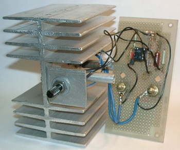
The power supplies are usually circuit to be tested by the power source, as long as it does more than 5 V provenance. (The B861 is still up to 3 V.) Resistors this capacity are curiously much more expensive than transistors, but you need a proper heat sink and can not change power sources burden.
Here it was easy to hole grid plate to set up a cold body, also was to T1 (isolated) attached.
The light-emitting diode D3 serves as the operating display as well as Z-diode.
There should be a red LED voltage because of smaller river, a green for better voltage stability, a reference element integrated B589 or TL431 is excellent spannungskonstant lights did not.


Electronic Load Circuit alternative link:


100W Darlington Transistor Amplifier Circuit 2+1 BDW83 BDW84 TDA8563
So far I’ve done the best work in projects diyebilirim.gerek very practical and efficient circuit design required a circuit in terms of quality.
BDW series I used the power transistors and integrated tda8563 tda1554 can also be used optionally. Power output as a 100w health a very simple circuit I used the audio output before I have done tda8563’ve used, but I tda1554 would recommend, ultimately our goal in this section is a powerful audio was not clean and a complementary audio almaktır.güç the 100w circuit will suffice.