Here is a distortion pedal, with noise-gate integrated setting and bass / medium / treble, operating on the sector. Personally I added a switch stop walking on food, a door fuse (fuse 500mA under glass) and led (220v) It is a fitting analog multiplexer controlled by two signals. One comes from the push through a memory removing rebounds parasite of the switch, the other from the floor noise-gate which compares the output level to a level
Distortion Pedal Guitar Effects

Distortion Pedal Effect Circuit Circuit Diagram
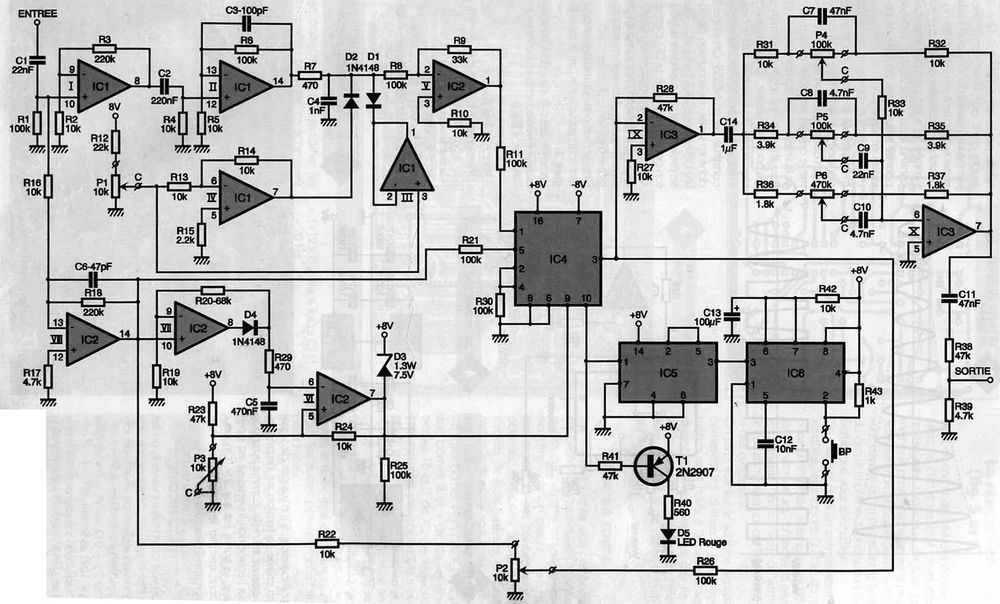
Part List
Resistors
– R1, R6, R8, R11, R21, R25, R26, R30: 100 Kohms
– R2, R4, R5, R10, R13, R14, R16, R19, R22, R24, R27, R31, R32, R33, R42: 10 Kohms
– R3, R18: 220 Kohms
– R7, R29: 470 ohms
– R9: 33 Kohms
– R12: 22 Kohms
– R15: 2.2 Kohms
– R17, R39: 4.7 Kohms
– R20: 68 Kohms
– R23, R28, R38, R41: 47 Kohms
– R34, R35: 3.9 Kohms
– R36, R37: 1.8 Kohms
– R40: 560 ohms
– R43: 1 kohm
Potentiometers
P1, P2, P3: 10 Kohms
P4, P5: 100 Kohms
P6: 470 Kohms
capacitors
C1, C9: 22nF
C2: 220nF
C3: 100pF
C4: 1nF
C5: 470nF
C6: 47 to 100pF
C7, C11: 47nF
C8, C10: 4.7nF
C12: 10nF
C13: 100µF 10V
C14: 1 µF LCC
C15, C18: 470µF 16V
C16, C17, C19, C20, C21, C22: 100nF
semiconductors
T1: 2N2907
D1, D2, D4: 1N4148
D3: Zener 1.3Watt 7.5Volt
D5: LED
IC1, IC2: TL084 or TL074
PD: diode bridge, round 0.5A
IC3: TL082 or TL072
IC4: CD4052
IC5: CD4013
IC6: NE555
IC7: LM7808
IC8: LM7908
Various
1 Transformer 2x9V 5 VA
1 printed circuit 12x8cm
2 6.35 mm mono jack sockets
1 box
Distortion Pedal Circuit for Guitar Effects PCB schematic alternative link:


Guitar Fuzz Factor X Circuit
Less material and a simple circuit schematic and PCB drawing simple pictures of the materials used are used for feeding the 9 volt battery in the unfoldment also added links
Fuzz Factor