I tested a simple and inexpensive serial pic programming circuit. The foundation mesh “JDM Programmer” pic of the programming circuit. RDC Programmer name resistors, diodes, capacitors, circuit test is based on the fact that I did with the PIC16F628 com cable directly from the PC using RS232 socket on the rear of the chassis I’ve used the program IC-Prog
There are a lot of programs on the programming card support, but inside there was rdc selected while JDM attempt did not trouble

Is lower than the cost for that use RS232 Cable also ned more healthy though occasionally communicates with the PC directly without an additional connection
Half the voltage on MCLR with 10k potentiometer can be adjusted to make adjustments I’ve programmed the PIC16F628
C1 100uF 16v circuits used in earlier versions of the healthiest I’ve tried the latest version 470uF 16v identified as stable value of using lower capacity


PIC Programmer Circuit Schematic
Contents

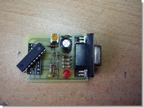
PIC Programmer Circuit PCB

To program the PIC16F84 can be programmed directly on the circuit PIC16F628 18-pin connector socket on the 11-16-17 placing it on the pins necessary programming can be canceled


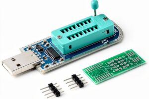
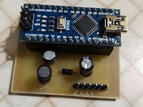
The finished version I tested the pic programmer photos


Source feng3.cool.ne.jp The site is closed on the page I’m adding descriptions
RCD Programmer
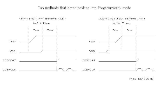
I believe that the “JDM Programmer” is cheap and very useful PIC Programmer. However, since “JDM Programmer” cannot control VDD, the algorithm “VPP before VDD” is inapplicable. Programming to the latest device from this reason may go wrong when using CONFIG settings as “Internal oscillator” “MCLR OFF”. These devices are given power from the “JDM programmer”,and execute program code. An error may come out by verification, or it may become impossible erasure and become impossible re-programming . In order to solve this problem, I designed a programmer based on the “JDM programmer.” Since this programmer was made of resistors, capacitors, and diodes, I named this the “RCD Programmer.” “Hardware settings” of IC-Prog are the same as the “JDM programmer.”
C1 is a charge pump capacitor*. This works voltage doubler. When TxD is negative voltage, C1 is charged through D7 from GND. If TxD carries out turn-on, since it will become positive voltage, the voltage charged in C1 is raised. The created high voltage is regulated by D7 to about 13V. If TxD carries out turn-on, both supply voltage will be created. CTS and RTS also join creation of supply voltage. This VDD is delayed and is applied by C2 and R4. D1-D5 are clump diodes. Since voltage drop is within the limits which can be disregarded, general purpose small rectifier is sufficient as the diode to be used. e.g. 1N4148,1S1588(Toshiba),1S2076A(Renesas or Hitachi),1S133(ROHM) . When not succeeding by the device which needs programming current like 16F84(A), the value of R3 is made small. Probably, it will be good using a trimmer resistor as R3.
After I published the RCD Programmer on my Web site, it has passed in one year. I obtained various questions about the RCD Programmer from many people. And Microchip newly developed Low-Pincount PICs which built in the memory exceeding 1k words. I recommend change capacity of C1 to 470uF now for stable programming.
*About general description of charge pump, please refer to DC/DC Conversion without Inductors(Maxim/Dallas Application Note 725). A important point is not a charge pump but controll of VDD in the RCD Programmer circuit. If this point is excluded, the JDM Programmer is far more excellent than the RCD Programmer. Because the RCD Programmer works by the pulse only once, the capacitor power cannot be continued for a long time.
Consideration for the computers which have poor surge protection (added: 2005-02-06 JST)
When you insert a RCD Programmer into the COM port of your computer during operation(“Hot Plug-in” or “Hot Socketing”), inrush current is generated. It seems that it is weak to an overcurrent and a short circuit although “EIA/TIA -562” is power saving and compatible with “EIA/TIA-232-E.” So, I added 200-ohm current limitation resistor. This resistor limits peak current and help computers which have poor surge protection circuit inside. However, the RCD programmer will not work well as for such a computer because the voltage of the COM port might be very low.
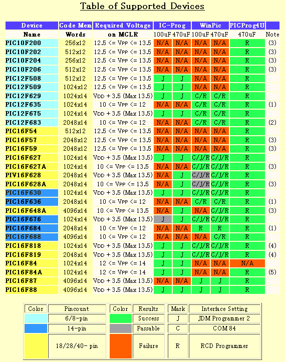
(1) WinPic– When both IntOSC and internal MCLR options are selected, programming is successful satisfactory. However, after exiting Program/Verify mode, the device may be unable to be read(or verify) correctly. Please feel easy ! The device can be Re-programmed.
(2)The Device ID of PIC12F683 is 0x0460. ID value “0x1280” shown in the data sheet(DS41204C) is not corrected for now(corrected in the autumn of 2004, DS41204D).
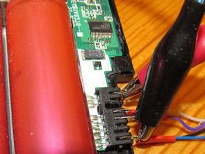
(3)Use an Adaptor, or ICSP Method for these devices ! Adaptor for SOT23 PIC10F2xx (example), for PIC16F57 (example), for PIC16F627A/628A/648A( See photo below).
(4)WinPic– Enable WinPic ‘s option “raise Vdd before MCLR=Vpp” !
(5)WinPic– Don’t use WinPic to programming to PIC16F84A with RCD Programmer! Use IC-Prog or PICProg4U!
Note: WinPic–The erasure and the re-programming might become impossible as for the devices afterwards when both IntOSC and internal MCLR options are selected besides by using WinPic that sets “InterfaceType” to “JDM Programmer 2”. In that case, please try after clearing all the check boxes in “Interface Test”.
Programming Software
IC-Prog Author: Bonny Gijzen
WinPic Author: Wolfgang Büscher
PICProg4U Author: FENG3
Requires .NET Framework 1.1 or later.
The available COM port and the RCD Programmer are detected automatically.
Supported devices are PIC10F200/202/204/206/220/222, PIC12F508/509/510, PIC16F54/57/59, PIC12F629/635/675/683, PIC16F627/628, PIC16F627A/628A/648A,PIC16F630/636/639/676, PIC16F684/685/687/688/689/690, PIC16F818/819, PIC16F84A, PIC16F87/88, PIC16F870/871/872/873/874/876/877, PIC16F873A/874A/876A/877A.)
Important !
Probably you should read “OSCCAL(internal OSCillator CALibration) word” and “BG(BandGap calibration) bits” in a device first, and should make a note of them on a piece of paper, before you start programming, so that it may not erase accidentally.
All OTP(One Time Programmable) devices and greater than 18-pin devices are not suppoerted !
Download
PCB and other files (PDF format) can be downloaded from here.
“Dongle” type RCD Programmer
Note: J5 is a jumper wire or a jumper resistor.
PCB Components layout
RCD Programmer which I always use
This board requires a 90°printed board mount D sub connector and a trim resistor. It is the size which can also mount 18pin TEXTOOL. Note: “0R” is a jumper wire or a jumper resistor.
PCB Components layout Bill Of Material
RCD Programmer for the computers whitch have poor surge protection
PCB Components layout Bill Of Material
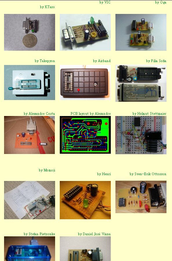
Various Examples RDC Programmer
FAQ
Q I have seen that there is a variable resistor in the circuit.Could you please explain how to calibrate this part or could you recommend a value which I have to turn the resistor?
A R3 value is 10k ohms for almost devices. But some old device such as PIC16F84A requires a little a lot programming current. Therefore, R3 value can be adjusted by using trimmer potentiometer since RCD Programmer Version 2.3(about 1k ohms or less, for PIC16F84A).
Q What is the resistor value “0R” ?
A “0R” is the zoro-ohm resistor. It is the jumper wire which have the shape of the resistor. Of course, ordinary jumper wire can be used as “0R”.
PIC16F84 00-99 Forward, Backward Counter Circuit Picbasic Pro
There are two pieces of counter circuit applications and other Picbasic Pro source code files available in proteus isis 00-99 7447 advanced counter display assembly PIC16F84 display (automatic)
PIC16F84 Counter Circuit Schematics
Hi Everybody,
We have understood the need to apply VPP before VDD to enter the Programming Mode.
In your text, you specify that the necessary delay is made thanks to the RC circuit consisting of C2-R4 (REM: C2 is however identified as C3 on the Feng3 Scheme !).
However, I do not understand how this bizarre RC circuit can induce any delay since no connection is applied to the capacitor’s terminals !?
And moreover, the VPP line is not even connected to this RC !?
Can you explain to me ?
Thanks in advance.