CH552G SPI and I2C Memory Programmer Minpro I V1.3. The CH552G-based Minpro I V1.3 programmer is a low-cost USB programmer used to read, write, and back up 24xx I2C EEPROM and 25xx SPI Flash memories. It is a practical solution especially for motherboard repair, BIOS flashing operations, small EEPROM copying tasks, and workshop-type memory recovery applications.
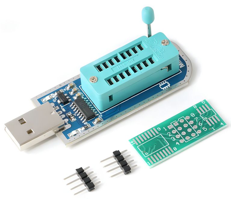
CH552G-based Minpro I V1.3 SPI I2C memory programmer
What Is the Minpro I V1.3 Programmer Used For?
Contents
- 1 What Is the Minpro I V1.3 Programmer Used For?
- 2 Supported Memory Types
- 3 25 SPI FLASH
- 4 24 EEPROM
- 5 Hardware Structure
- 6 5V and 3.3V Logic Level Issue
- 7 Using 1.8V Flash Memory
- 8 Software and Driver Installation
- 9 Points to Consider During SPI Flash Reading and Writing
- 10 Problems Encountered in I2C EEPROM Programming
- 11 Firmware Update and DFU Mode
- 12 Comparison with CH341A and EZP Programmers
- 13 Practical Checklist for Workshop Use
- 14 Technical Summary
- 15 Who Is It Suitable For?
24xx series EEPROM memories and 25xx series SPI Flash memories are used in many devices, from television motherboards to modems, automotive modules, and computer BIOS circuits, to store settings, firmware, or calibration data.
An external programmer is required to understand whether these types of memories are faulty, to back up their contents, or to write new data.
Minpro I V1.3 connects to the computer via USB and communicates with memory ICs through the CH552G microcontroller.
Since the hardware SPI line is used on the 25xx SPI Flash side, the operation speed may be better than simple bit-bang solutions.
On the 24xx I2C EEPROM side, communication is carried out through software because the CH55x family does not include a hardware I2C block.
Similar-purpose CH341A programmer tools previously used are also in the same work group. However, the use of the CH552G on the Minpro I board makes it a separate subject of examination, especially in terms of firmware updates and trying different software.
Supported Memory Types
The main target of the programmer is two main memory families:
- 24xx series I2C EEPROM memories
- 25xx series SPI Flash memories
EEPROM ICs such as 24C02, 24C04, 24C08, 24C16, 24C32, 24C64, 24C256, and 24C512 are common for storing small setting data.
SPI Flash memories such as 25Q32, 25Q64, and 25Q128 can be used for BIOS, modem firmware, LCD TV software, or embedded system boot data.
The program list may include many models from manufacturers such as AMIC, Atmel, EON, GigaDevice, MXIC, PMC, SST, ST, Winbond, Microchip, ROHM, NXP, and similar manufacturers.
Still, in practice, relying only on the model name in the software list is not sufficient. The exact code on the IC, supply voltage, and pinout must definitely be compared with the datasheet.
Older projects such as I2C, SPI, and NVM EEPROM programmer circuits may also be useful for comparison for different programmer examples focused on SPI, I2C, and EEPROM.
25 SPI FLASH
| Manufacturer | Supported Models |
|---|---|
| AMIC | A25L05P, A25L05PT, A25L512, A25L10P, A25L010, A25L020, A25L20P, A25L40P, A25L040, A25L080, A25L80P, A25L16P, A25L016, A25L032 |
| ATMEL | AT25F512, AT25F512B, AT25F512A, AT25F1024, AT25FS010, AT25F1024A, AT25F2048, AT25DF021, AT25DF041A, AT25F4096, AT26F004, AT26DF041A, AT25FS040, AT26DF081A, AT26DF161A, AT25DF161, AT26DF161, AT26DF321, AT25DF321A, AT25DF321, AT25DF641 |
| EON | EN25B05, EN25F05, EN25B05T, EN25P05, EN25LF05, EN25F10, EN25P10, EN25D10, EN25LF10, EN25D20, EN25LF20, EN25F20, EN25F40, EN25D40, EN25LF40, EN25T80, EN25D80, EN25Q80, EN25F80, EN25P80, EN25Q16, EN25H16, EN25B16T, EN25F16, EN25D16, EN25T16, EN25B16, EN25F32, EN25P32, EN25B32, EN25Q32, EN25B32T, EN25B64T, EN25Q64, EN25F64, EN25B64, EN25F128, EN25Q128 |
| ES | ES25P40, ES25P80, ES25P16 |
| ESMT | F25L04UA, F25L004A, F25L08PA, F25L008A, F25L016A, F25L16PA, F25L32PA, F25L32QA, F25L64QA |
| GIGADEVICE | GD25Q512, GD25Q10, GD25Q20, GD25Q20, GD25D40, GD25Q41, GD25F40, GD25Q40, GD25D80, GD25F80, GD25Q80, GD25T80, GD25Q16, GD25Q32, GD25Q64, GD25Q128 |
| KH | KH25L4006E, KH25L8036D, KH25L8006E, KH25L1606E |
| MSHINE | MS25X40 |
| MXIC | MX25V512, MX25L512, MX25L1005, MX25L2005, MX25L2026, MX25U4035, MX25V4035, MX25L4005A, MX25V4005, MX25L8005, MX25V8006E, MX25V8005, MX25U8033E, MX25L8036E, MX25V8035, MX25L8035E, MX25U8035, MX25L8006E, MX25L1636E, MX25L1606E, MX25L1633E, MX25L1608D, MX25L1635E, MX25U1635E, MX25L1605D, MX25L1608E, MX25L1636D, MX25L3225D, MX25L3237D, MX25L3236D, MX25L3206E, MX25L3205D, MX25U3235E, MX25L3208D, MX25L3235D, MX25U3235F, MX25L3208E, MX25L6455E, MX25L6408D, MX25L6465E, MX25L6408E, MX25L6406E, MX25L6445E, MX25L6405D, MX25L6436E, MX25L6406, MX25L12865E, MX25L12835E, MX25L12836E, MX25U12835F, MX25L12835F, MX25L12855E, MX25L12845E, MX25L12805D, MX25L25635E/F, MX25L25639F, MX25L25735E/F, MX25U25635F, MX25L2573, MX66L51235F, MX66U5123F |
| PMC | PM25LV512A, PM25LV010A, PM25LV020, PM25LV040, PM25LV080B |
| SPANSION | S25FL001, S25FL040, S25FL002, S25FL004, S25FL008, S25FL160, S25FL016, S25FL032, S25FL064, S25FL128 |
| SST | SST25VF512A, SST25VF512, SST25VF010A, SST25VF010, SST25VF020, SST25VF020A, SST25VF040B, SST25VF040, SST25VF040A, SST25VF080B, SST25VF016B, SST25VF032B, SST25VF064C |
| ST | M25P05A, M25P10A, M25P20, M25P40, M25PX80, M25PE80, M25P80, M25PE16, M25P16, M25PX16, M25PX32, M25P32, M25PE32, M25P64, M25PE64, M25PX64, M25P128 |
| WINBOND | W25P10, W25X10A, W25X10AL, W25X10L, W25X10, W25X20A, W25X20L, W25X20, W25X20AL, W25P20, W25Q40BV, W25X40, W25X40AL, W25X40L, W25X40A, W25P40, W25P80, W25Q80BV, W25X80L, W25X80A, W25X80AL, W25Q80V, W25X80, W25X16, W25Q16BV, W25Q16V, W25P16, W25P32, W25Q32V, W25X32, W25Q32BV, W25Q64BV, W25X64, W25P64, W25Q128FV, W25Q128BV, W25Q256FV |
24 EEPROM
| Manufacturer | Supported Models |
|---|---|
| ATMEL | AT24C01, AT24C01A, AT24C01B, AT24C02, AT24C02A, AT24C02B, AT34C02D, AT24C04, AT24C04A, AT24C04B, AT34C04, AT24C08, AT24C08A, AT24C08B, AT24RF08C, AT24C16, AT24C16A, AT24C16B, AT24C32, AT24C32A, AT24C32B, AT24C64, AT24C64A, AT24C64B, AT24C128, AT24C128A, AT24C128B, AT24C256, AT24C256A, AT24C256B, AT24C512, AT24C512A, AT24C512B, AT24C1024, AT24C1024A, AT24C1024B |
| CATALYST | CAT24C01, CAT24C02, CAT24C04, CAT24C08, CAT24C16, CAT24C32, CAT24C64, CAT24C128, CAT24C256, CAT24C512, CAT24C1024 |
| GENERIC | 24C01, 24C02, 24C04, 24C08, 24C16, 24C32, 24C64, 24C128, 24C256, 24C512, 24C1024 |
| FAIRCHILD | FM24C01, FM24C02, FM24C03, FM24C04, FM24C05, FM24C08, FM24C09, FM24C16, FM24C17, FM24C32, FM24C64, FM24C128, FM24C256, FM24C512, FM24C1024 |
| HOLTEK | HT24C01, HT24LC01, HT24C02, HT24LC02, HT24C04, HT24LC04, HT24C08, HT24LC08, HT24C16, HT24LC16, HT24C32, HT24LC32, HT24C64, HT24LC64, HT24C128, HT24LC128, HT24C256, HT24LC256, HT24C512, HT24C1024 |
| ISSI | IS24C01, IS24C02, IS24C04, IS24C08, IS24C16, IS24C32, IS24C64, IS24C128, IS24C256, IS24C512, IS24C1024 |
| MICROCHIP | 24AA01, 24FC01, 24LC01, 24AA02, 24FC02, 24LC02, 24AA04, 24FC04, 24LC04, 24AA08, 24FC08, 24LC08, 24AA16, 24FC16, 24LC16, 24AA32, 24FC32, 24LC32, 24AA64, 24FC64, 24LC64, 24AA128, 24FC128, 24LC128, 24AA256, 24FC256, 24LC256, 24AA512, 24FC512, 24LC512, 24AA1026, 24FC1026, 24LC1026 |
| NSC | 24C02, 24C02L, 24C64 |
| NXP | PCA24S08 |
| RAMTRON | FM24C04A, FM24CL04, FM24C16A, FM24CL16, FM24C64, FM24CL64, FM24C256, FM24CL256, FM24C512 |
| ROHM | BR24C01, BR24L01, BR24T01, BR24C02, BR24L02, BR24T02, BR24C04, BR24L04, BR24T04, BR24C08, BR24L08, BR24T08, BUL08, BR24C16, BR24L16, BR24T16, BR24C32, BR24L32, BR24T32, BR24C64, BR24L64, BR24T64, BR24T128, BR24T256, BR24T512, BR24T1M |
| SANYO | LE26CAP08 |
| ST | M24C01, ST24C01, M24C02, ST24C02, M24C04, ST24C04, M24C08, ST24C08, M24C16, ST24C16, M24C32, ST24C32, M24C64, ST24C64, M24128, M24256, M24512, M24M01, M24M02 |
| XICOR | X24C01, X24C02, X24C04, X24C08, X24C16 |
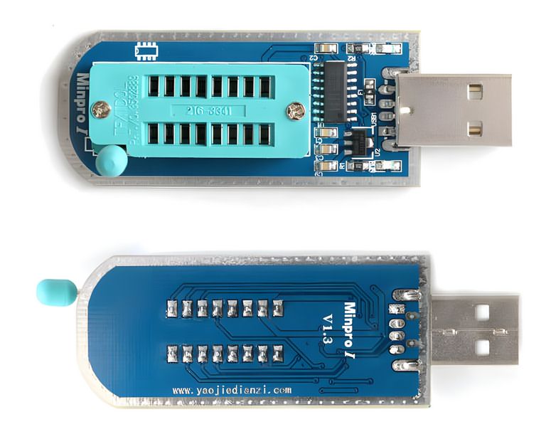
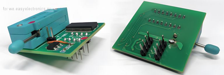
Hardware Structure
The Minpro I V1.3 board does not have very complex hardware.
The main structure consists of the CH552G microcontroller, USB connection, ZIF socket, SOIC adapter connections, a few passive components, and lines that manage the memory supply.
Although it looks simple, special attention is required especially for the logic level issue.
CH552G Microcontroller
CH552G is the main controller that manages the USB connection and memory programming operations. When the board is connected to the computer, this IC is the side that communicates with the software.
During SPI Flash programming, the memory IC is connected to the SPI lines of the CH552G.
Therefore, the operation speed with 25xx memories may be more advantageous than fully software-based methods.
The situation is different on the I2C EEPROM side. Since CH55x controllers do not have a hardware I2C interface block, the SDA and SCL lines are driven by software.
This method works, but it should not be expected to be as fast as hardware I2C. Since EEPROM ICs generally have small capacities, this speed difference does not create a serious problem in most applications.
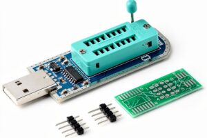
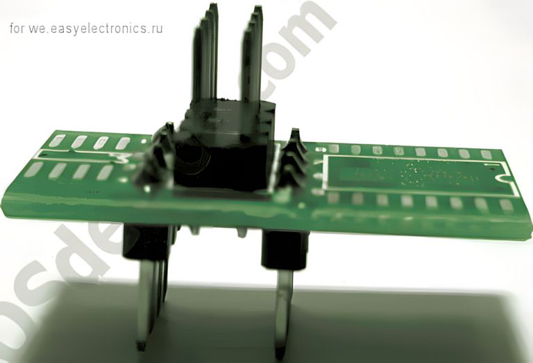
ZIF Socket and Adapter Board
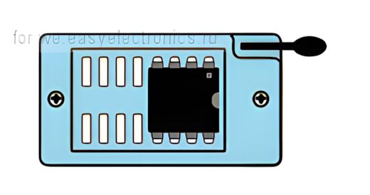
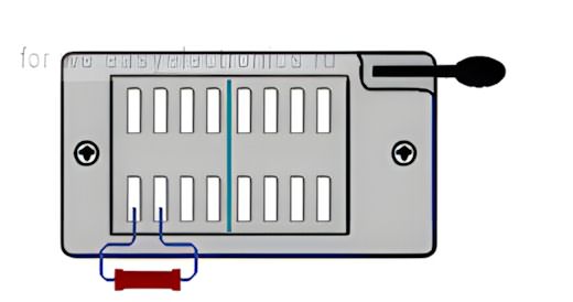
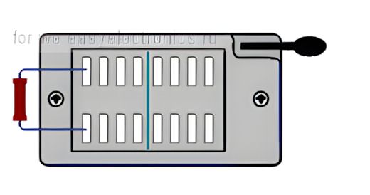
There is a ZIF socket on the programmer for placing the memory IC.
In the source circuit, only a certain part of the ZIF socket is used for both memory types.
Therefore, when placing the IC into the socket, attention should be paid to the markings on the board and the pinout in the software.
An adapter board is used for SOIC-packaged memories.
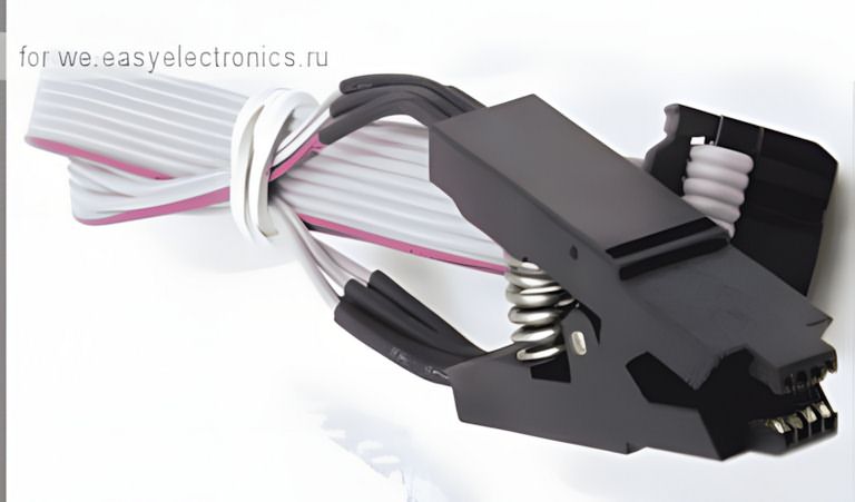
The healthiest method is to solder the IC to a suitable SOIC adapter or use a quality SOIC test clip.
Clamps, paper clips, or temporary pressure methods may work in short tests; however, if contact resistance increases, read errors, verification errors, or partial write problems may occur.
The adapter board also includes an additional connector area used for programming cable or test clip connection.
This connection can be especially useful for those who want to read the IC without removing it from the board; however, when programming on-board, the power state of the target circuit must definitely be checked.
If a more universal solution is sought in the workshop, circuits supporting multiple protocols such as universal programmers with Atmel, Microchip, SPI, and I2C EEPROM support can also be examined.
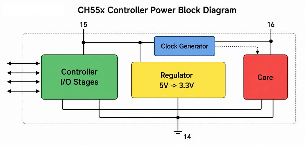
5V and 3.3V Logic Level Issue
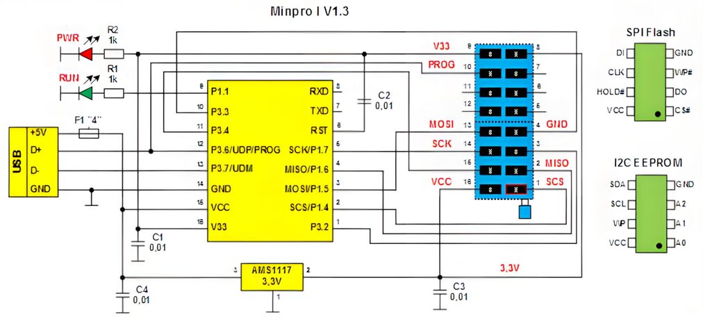
One of the most important technical points of the board is the CH552G power structure. In the source circuit, 5V from the USB line is applied to the internal regulator input of the CH552G, that is, the VCC side.
The V33 output is filtered with a capacitor. This structure is compatible with the CH55x datasheet logic; however, it should be considered separately in terms of the logic levels going to the memory ICs.
When the I/O stages of the CH552G operate connected to the 5V side, signal levels close to approximately 5V may occur at the memory inputs.
Since some 24xx and 25xx memories have 5V-tolerant inputs, this may not cause a problem.
However, direct connection is risky especially with modern 3.3V SPI Flash or 1.8V Flash memories.
| Memory Type | Typical Supply | Point to Consider |
|---|---|---|
| 24xx EEPROM | 3.3V or 5V | The model’s 5V tolerance should be checked through the datasheet |
| 25xx SPI Flash | Generally 3.3V | 5V logic level may cause permanent damage in some ICs |
| 1.8V SPI Flash | 1.8V | A 1.8V adapter or suitable level shifter must definitely be used |
For the CH552G, the way to pull input/output levels to 3.3V according to the datasheet is to use pin 15 VCC and pin 16 V33 appropriately and provide supply from an external 3.3V regulator.
However, this change may affect the firmware update side; because in some cases there is a 5V requirement on the VCC line for the controller to enter programming mode.
Therefore, if the board will be modified, not only the memory read-write side but also the DFU and firmware update side should be considered together.
Using 1.8V Flash Memory
1.8V SPI Flash memories are especially encountered in new-generation motherboards, laptops, and some low-power devices.
These ICs may not tolerate 3.3V or 5V signals. To work with 1.8V memory on simple programmers such as Minpro I, a separate 1.8V adapter must be used.
The 1.8V adapter is used not only to reduce the supply voltage, but also to move the logic level of the SPI lines into the safe range of the memory IC.
Without an adapter, making a temporary connection with the approach of “let me read it once” is risky.
Incorrect voltage may cause the memory to fail completely or make its contents unreadable.
In some adapters, the 1.8V regulator input and output can be bridged with a jumper to make it suitable for the 3.3V level.
If such use will be made, the adapter circuit should be inspected visually, and which line the jumper actually shorts should be verified with a measuring instrument.
Software and Driver Installation
Driver and programming software are required for the Minpro I V1.3 programmer to operate on the computer side.
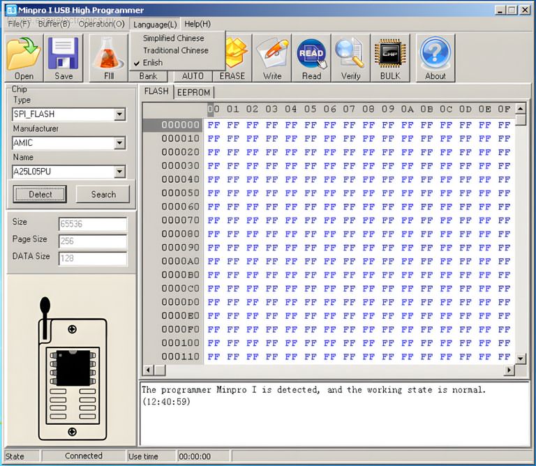
In the source content, the software appears under the name “Minpro I USB High Programmer.” The basic order for installation is as follows:
- The program archive is extracted to the computer.
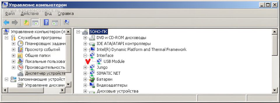
- The programmer is plugged into the USB port.
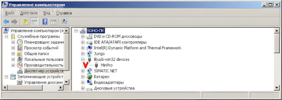
- A device similar to “MinPro” with a missing driver appears in Device Manager.
- The program folder is manually shown from the driver update screen.
- When the driver is installed, the device appears under libusb-win32 devices.
- The program interface is opened by running MinproI.exe.
On first startup, the interface may appear in Chinese. It is possible to switch to the English interface through the menu.
When the programmer is recognized correctly, connection information appears in the status window of the software.
The point to pay attention to on the driver side is that some packages may not have a digital signature.
Depending on the Windows version, an unsigned driver warning may be received. In such a case, attention should be paid to the source of the driver, and random driver installation from unknown archives should not be performed.
The USB PIC, Atmel, I2C, and SPI EEPROM programmer article is also a close example for similar USB-based programmer logic.
Points to Consider During SPI Flash Reading and Writing
Making an incorrect operation on SPI Flash memories can make not only the memory but also the device to which it is connected inoperable.
Especially if BIOS or device firmware is being read, the first operation should always be to make a backup.
- First read the memory and save the file.
- Read the same memory a second time and compare it with the first file.
- If the two read files are not the same, do not proceed to writing.
- After writing, definitely perform verify confirmation.
- Make sure that the WP and HOLD pins are at the correct level.
- If programming on-board, check the supply line of the target circuit.
If programming is performed while the memory is on the board, the programmer and target device should not supply power at the same time.
Otherwise, 3.3V or 5V coming from the programmer may back-feed other lines of the device. This may damage both the programmer and the target board.
Problems Encountered in I2C EEPROM Programming
24xx EEPROM ICs look simple; however, wrong model selection is a common mistake due to addressing and capacity differences.
For example, although 24C02 and 24C16 are from the same family, their addressing structure and memory organization are different.
When the wrong model is selected in the program, the read operation may appear as empty, repeating, or faulty data.
Points to consider in I2C EEPROM programming:
- SDA and SCL lines should be connected correctly
- The GND line should make solid contact
- A0, A1, A2 address pins should be evaluated according to the connection on the board
- The WP pin should be at the appropriate level for writing
- The file size after reading should match the selected EEPROM capacity
If the EEPROM IC is read while it is on the circuit, the microcontroller or other peripheral components connected to it may affect the SDA/SCL lines.
In this case, removing the IC and reading it gives more reliable results.
Firmware Update and DFU Mode
DFU mode is used for firmware updates on boards with the CH552G controller.
In the source information, it is stated that a resistor in the range of 10k to 22k can be connected between the V33 pin and UDP pin to enter DFU mode.
This resistor allows the microcontroller to enter the special boot mode when power is applied.
If these pins can be accessed from the unused part of the ZIF socket on the board, the process becomes easier.
However, before making the connection, the pin numbers must definitely be verified.
Connecting a resistor to the wrong pin may stress the USB line, regulator output, or microcontroller.
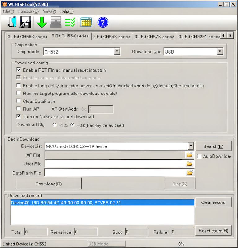
In DFU mode, a different USB device may appear on the computer side. In the source example, VID 4348 and PID 55E0 information is mentioned.
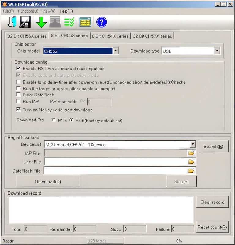
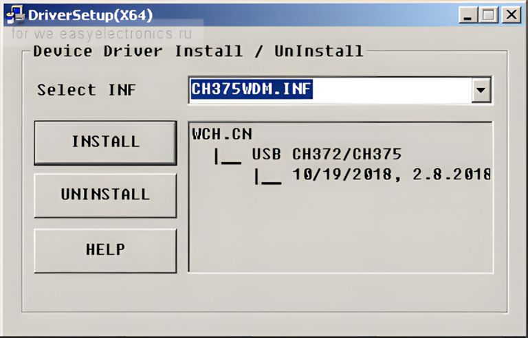
The WCHISPTool utility is used for firmware loading for the CH55x family.
After WCHISPTool is installed, the required CH375 driver may also need to be installed separately.
The safest approach in the firmware update process is to first investigate the possibility of backing up the existing firmware and to load only verified files.
The standard bootloader may not always provide the ability to read flash. Even if reading can be done with third-party dumper tools, this process is not a routine step for a normal user and can make the board inoperable if used incorrectly.
Comparison with CH341A and EZP Programmers
CH341A is one of the most commonly used programmers in low-cost EEPROM and SPI Flash operations.
Minpro I V1.3 offers a different option with its CH552G-based structure. In the source content, it is stated that Minpro I may be faster than CH341A on the SPI Flash side, while no speed advantage should be expected on the I2C EEPROM side.
The CH552G is also used in some programmers such as EZP2019 and EZP2020. Since the EZP series has a longer development history, the supported memory list may be wider.
Methods such as editing the MinproI.Dat file or transferring memory definitions from the EZP side are mentioned on the internet; however, such changes are not risk-free enough to be recommended directly.
Incorrect memory definition, faulty algorithm, or incompatible page write time may cause data corruption.
If the user will only work with common Winbond, MXIC, GD25, or AT24C series memories, Minpro I can do the job.
If a wider device list, better software support, and continuous updates are desired, professional programmers or more advanced universal models should be preferred.
Practical Checklist for Workshop Use
A few simple checks before using the programmer reduce time loss and memory damage:
- Read the exact code on the memory with a magnifier.
- Check the supply voltage with the datasheet.
- If using a SOIC clip, check the pin 1 direction again.
- Perform the read operation at least twice and compare the files.
- Before writing, store the original dump file in a separate folder.
- Select the correct manufacturer and model in the programmer software.
- If programming on-board, make sure the target board is de-energized.
The most common mistake in memory programming is writing new data without verifying the first read file.
Especially in BIOS and firmware repairs, if there is no good backup, returning becomes difficult. Therefore, reading, comparison, and verify steps should not be skipped.
Technical Summary
| Feature | Description |
|---|---|
| Main controller | CH552G |
| Computer connection | USB |
| Main supported memories | 24xx I2C EEPROM, 25xx SPI Flash |
| SPI communication | Through CH552G hardware SPI line |
| I2C communication | By software bit-bang method |
| Software | Minpro I USB High Programmer |
| Firmware tool | WCHISPTool |
| Risky point | Logic level compatibility in 3.3V and 1.8V memories |
Who Is It Suitable For?
Minpro I V1.3 is suitable for users who are looking for a low-cost memory programmer and occasionally work with 24xx EEPROM and 25xx SPI Flash ICs.
It can be used to back up or rewrite memories in televisions, modems, motherboards, control boards, and small embedded systems.
In a more professional working setup, socket quality, software support, supported IC list, and logic level safety become more important.
If continuous BIOS repair, automotive EEPROM operations, or work with many different memory families will be performed, more advanced programmers should be preferred.
For those interested in the microcontroller programming side, different USB programmer projects such as the Atmel AVR USB programmer also provide a useful comparison.
Memory programming and microcontroller programming are not the same thing; however, basic points of attention such as USB driver, firmware, target voltage, and pin connection are similar.
The most critical usage note for Minpro I V1.3 is not to underestimate the operating voltage of the memory IC.
A connection that does not cause problems with older 5V-tolerant EEPROMs may create risk in modern 3.3V or 1.8V SPI Flash ICs.
When the correct adapter, correct model selection, and verified read-write sequence are applied, this CH552G-based board can be a useful helper for hobby and repair workshops.
Source: we.easyelectronics.ru/part/programmator-spi-i-i2c-mikroshem-pamyati-minpro-i-v13-na-ch552g.html (closed)
CH372 driver, MinPro_I.bin, MinproI V1.1.3, WCHISPTool Setup files;