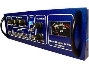
Completed class d amplifier project Class d power amp, preamp, vu meter, psu, panel desing. Learn about design of amplifiers in class D. Design amplifier wiring for bass with a power output of about 100 W. Complete the output stage with an active correction preamp with with a three-band equalizer and a switchable center band correction frequency. Wiring characteristics simulate in PSpice and design printed circuit boards in Eagle.
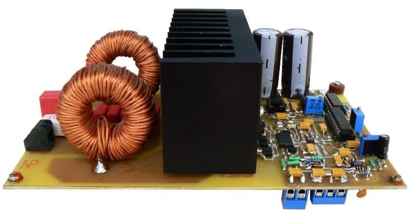
Based on previous circuit designs, implement a functional sample of the power amplifier for bass of prescribed parameters, including correction preamplifier and power supply unit.
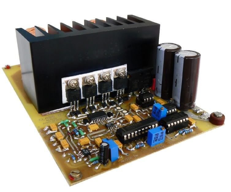
Amplifier revive and measure its basic characteristics, compare the results with the parameters expected with computer simulation results.
The LT1358 error amplifier circuit is applied audio signal with amplitude of 1V and frequency of 1kHz. The output signal of this circuit is compares in comparator LT1394 with triangular voltage with amplitude +/- 4V and a period of 20us, corresponding to a frequency of 50kHz. This frequency is for illustrative graphs chosen lower than in the real connection.
The circuits are supplied symmetrically +/- 5V. IN At the top of the picture you can see the waveform of the input audio signal, in the middle the waveform inverted voltage after passing the LT1358 circuit and comparing it to modulation with a triangular signal and at the bottom the output voltage from the comparator.
Schematic Class D Bass Guitar Amplifier Circuit
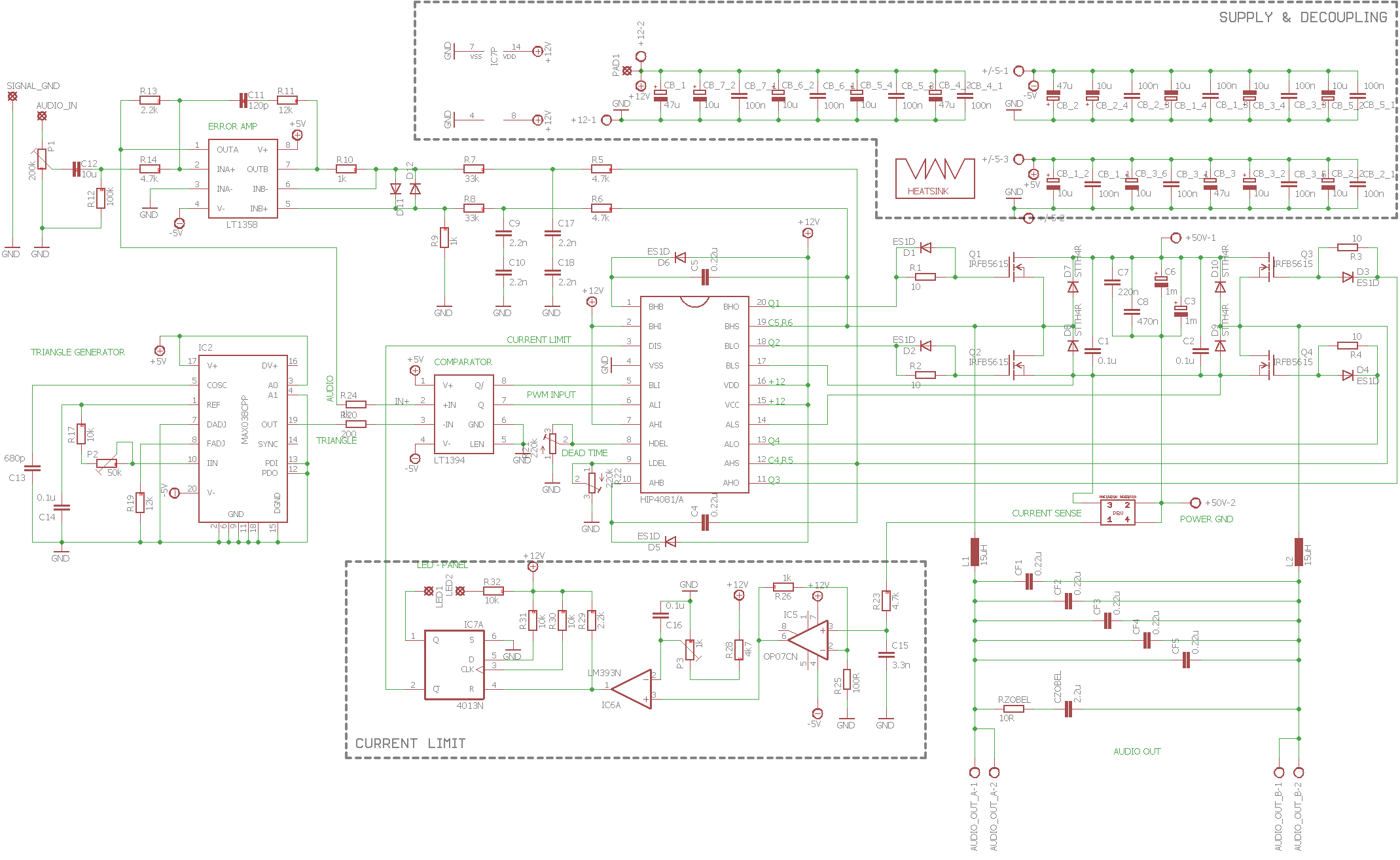
At the beginning of the design it was considered to use the HIP4080A circuit that it offers an interesting solution, as it has an integrated input comparator in the case unfortunately, it does not reach the quality of the external comparator in terms of its accuracy, delays, speeds, and the like.
More information about the comparator used was described in chapter 3.3.2. At the time of this work, the circuit was not available from suppliers and could not be sent as a sample directly from the manufacturer.
They are key to achieving high amplifier efficiency and reproduction quality terminal transistors that act as switches. The connection of transistors should achieve the lowest power loss, low latency and capability fast switching of inductive power load.
Connection of output stage as it was indicated earlier is a full bridge type, consisting of 4 induced MOSFETs As the load remaining with the output LC filter and speaker is strongly inductive, its switching creates overvoltage spikes, which should eliminate integrated anti-parallel diodes. Several transistors meet these requirements HEXFET from International Rectifier.International Rectifier HEXFET parameters, below calculated theoretical power losses at the output stage. All transistors are in TO-220 cases.
FILE DOWNLOAD LINK LIST (in TXT format): LINKS-26266.zip


Circuit d’amplificateur de guitare basse de classe D
Projet d’amplificateur de classe d terminé Ampli de puissance de classe d, préamplificateur, vu-mètre, alimentation, panneau de conception. Apprenez-en plus sur la conception des amplificateurs de classe D.Configurez le câblage de l’amplificateur pour les basses avec une puissance de sortie d’environ 100 W. Complétez l’étage de sortie avec un préamplificateur de correction actif avec un égaliseur à trois bandes et une fréquence de correction de bande centrale commutable. Les caractéristiques de câblage simulent dans PSpice et conçoivent des cartes de circuits imprimés dans Eagle.
Sur la base des conceptions de circuits précédentes, implémentez un échantillon fonctionnel de l’amplificateur de puissance pour les graves des paramètres prescrits, y compris le préamplificateur de correction et le bloc d’alimentation.
L’amplificateur ravive et mesure ses caractéristiques de base, compare les résultats avec les paramètres attendus avec les résultats de la simulation informatique.