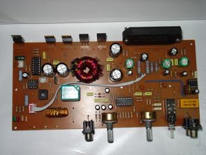
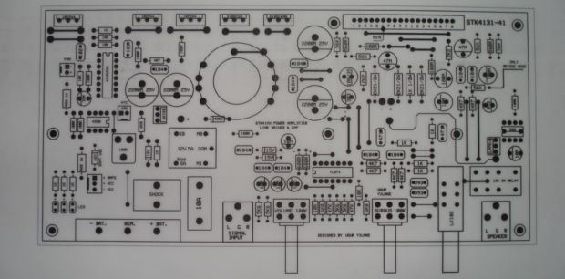
Complete car amp in a project stk4131 amp solid-II solid KA3525A DC-DC converter (SG3525) is located in the Filter section based on the bass opampli also tl074 DC-DC converter, the primary windings of the transformer circuit used; 2×6 2x type 9 secondary species (connected in parallel with wire Section 2 1mm) of the circuit diagram I do not have expresspcb source prepared with a program writes the values of all the materials on the PCB there is PCB drawing
eproje forums @northeastern PCB design is a circuit that is shared by ugur Yilmaz made by fasting. Thank you to the people who contributed to prepare
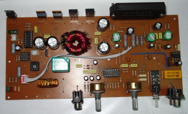
Quote; Smps + Out + Delay + Lpf + thermal fan Driver circuit by adding the last has become. After removing the PCB, Plug-and-play installation with a successful performance exhibits.The NTC 47k on the PCB should be mounted on the heatsink close to the chip as shown with the cable.When the temperature exceeds 40C, the fan is automatically activated, and until this has been down to working temperature.Automatically activated when heat falls below 40C.
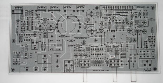
Previous applications of this work are used in different circuits assembled on a PCB that is a form of.For this reason, I didn’t put into the schema file.
Our show circuit voltage of PCB for 3 LEDs in the bottom left corner I added.These LEDs +13.8 V battery Input + and – voltage on the supply lines allows you to see.
expresspcb : http://www.expresspcb.com/ExpressPCBHtm/Download.htm
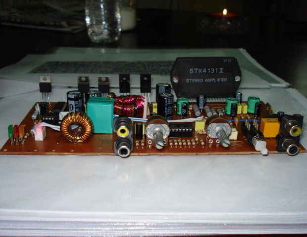
STK4131-II pcb:
FILE DOWNLOAD LINK LIST (in TXT format): LINKS-25460.zip


12V 7ah 1.3Ah battery charging regulator circuit with L200
the Battery Charger circuit (lead acid SLA) L200 regulator chip on the circuit board resistor and the diode on the positive 1.3 Ah or 7AH batteries or you can charge with the change of the commutator of the PCB and edit the drawing, by adding the jumper, you can make gradual Proteus ISIS Proteus Ares PCB circuit.. with a schematic drawing of the battery charging prepared with the source drawing files.
The battery charging circuit performs a @pvvm.c thanks to people who contributed to preparing comments below @pvvm.c belongs to my teacher.
Battery Charger circuit diagram
Auto-Verstärker-Schaltung mit STK4131-II
Komplette car-amp in einem Projekt stk4131 amp solid II solid KA3525A DC-DC-Wandler (SG3525) befindet sich in der Filter-Sektion basierend auf den bass opampli auch tl074 DC-DC-Wandler, der Primärwicklungen des Transformators Schaltung verwendet wird; 2×6 2x Typ 9 sekundäre Arten (parallel geschaltet mit Draht-Abschnitt 2 1mm) von der Schaltplan, die ich nicht habe expresspcb Quelle vorbereitet mit einem Programm schreibt die Werte aller Materialien, die auf der platine gibt es PCB-Zeichnung
eproje Foren @nordöstlichen PCB-design ist eine Schaltung, die geteilt durch ugur Yilmaz aus durch Fasten. Danke an die Menschen, die dazu beigetragen vorbereiten