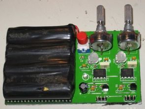
Servo motor test circuit the same simple structure made of circuit ne555 timer IC 2 piece disabled based on servo motor can be used in different applications depending on the situation or the test writer to run the circuit 4 x 1.2 v rechargeable batteries, used by linking instead of the 5v adapter serial Servo Motor can be run in the Test Circuit.


Source: keirle.com/2_test/servo_tester/servo_tester.htm alternative link:
FILE DOWNLOAD LINK LIST (in TXT format): LINKS-19635.zip


Volt amp meter circuit PIC16F877
graphic lcd Volt amp meter circuit pic16f877 microcontroller Board, with the addition of the mc34063 dc-dc converter circuits and the l5973 used in the screenshot lm324 opamp GLCD MTG-12864B current and voltage information displaying. GLCD Volt ampere Meter circuit PCB is not a drawing but GLCD amps volts meter circuit source C, hex codes and circuit diagram.
Einfacher Zweikanal-Servomotor-Testkreis 555
Servomotor Testschaltung die gleiche einfache Struktur aus Schaltung ne555 Timer IC 2 Stück deaktiviert basierend auf Servomotor kann in verschiedenen Anwendungen je nach der Situation oder der Testschreiber verwendet werden, um den Stromkreis 4 x 1,2 V wiederaufladbare Batterien, verwendet durch Verknüpfung statt des 5V-Adapters kann der serielle Servomotor in der Testschaltung betrieben werden.