Some battery-powered electronic devices are designed for occasional use. Users often forget to turn them off, which causes the battery to drain quickly. In particular, some multimeters lack an automatic shut-off feature. The biggest advantage of this circuit is its very low current consumption.
An automatic battery shut-off device is a type of automatic switch that cuts off the voltage after a predetermined period of time. The circuit can be integrated into a larger device or used as an adapter connecting the battery to the receiver it powers.
Controlling the power flow is simple: pressing the button applies power and simultaneously activates the timer. Pressing the button again during the operating cycle extends the operating time.
Automatic Power Switch Features
Contents
Operating time is adjustable.
MOSFET controlled.
LED status indicator.
Quiescent current consumption 1uA.
Maximum operating current 10A (TO220 MOSFET).
Power supply 6-15 V.
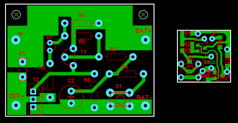
PCB board dimensions 44x33mm (DIP) SMD-DIP 17.1×16.7mm
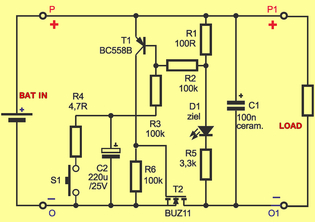
Instead of a standard mechanical power switch or relay, the circuit uses a MOSFET transistor such as BUZ10, BUZ11, IRF530, or IRF540 power MOSFET with a resistance of 0.05W or less and an operating current of more than 20A.
Operation of the Automatic Voltage Cut-off Circuit
When the S1 button is pressed, the charged capacitor C2 discharges, and after releasing the button, the capacitor charges very slowly with the current passing through the base circuit of the transistor and the R3 100K resistor. This current turns on the T1 BC558 transistor, and a positive supply voltage is applied to the R6 100K resistor and the gate of the MOSFET.
This voltage fully turns on the MOSFET, meaning that the battery voltage is applied to the connected device, the load. The D1 LED also lights up. The current passing through this diode creates a small voltage drop (0.15-0.4 V) across the R1 resistor. This voltage creates a positive feedback signal and helps to turn on the BC558 transistor.
However, when the charging current of the C2 220uf capacitor drops significantly over time, the BC558 transistor begins to disconnect, the voltage across the R6 100K resistor drops, and the MOSFET also begins to disconnect.
Lowering the output voltage reduces the voltage drop across the R1 100-Ohm resistor, which accelerates the disconnection process. Consequently, after a certain period, the output voltage drops within a very small fraction of a second.
Without the positive feedback provided by the R1 resistor, the output voltage drop would be very slow, which is unacceptable. In the steady state, both transistors are disconnected, and the C2 220uf capacitor charges to full battery voltage. The circuit draws almost no current; only the zero currents of the transistors and the leakage current of the C2 capacitor flow, but these are negligibly small currents on the order of nanoamperes.
A k100nF capacitor is added to the switch output. This capacitor will prevent the connected device from self-exciting. If desired, the capacitance of C1 can be increased to 220-470 uF, in which case the diode D1 will smoothly switch off in a second or longer, rather than a fraction of a second, and the voltage across points P1 and O1 will also decrease.
The basic version of the circuit is designed to operate with battery voltages between 6V and 16V. For lower voltages, a MOSFET with a lower threshold voltage should be used. Operation with batteries above 16V is not recommended; this is because of the MOSFET’s allowed gate-source voltage, not the nominal voltage of C2.
Automatic Battery Switch Circuit Diagram
Testing and Timing the Automatic Battery Switch Circuit
First, replace the 220uF capacitor with a 10uF capacitor. When the switch is pressed, the green LED will light up and turn off after approximately 5-6 seconds. While the LED is lit, the output receives the full battery voltage.
After verifying that the 10uF capacitor is working, you can solder a capacitor with a capacitance that provides the desired on-time. 100 microfarad provides one minute of on-time. 220uF provides approximately two minutes of on-time.
In practice, these times can vary significantly due to the wide tolerance range of electrolytic capacitors, even between -20% and +50%.
During operation, the circuit draws the same amount of current as the LED, approximately 2mA with a 9V power supply. However, in standby mode, the module draws almost no current.
Note: PCB drawings have been checked but not tested. I used SOT23 package MOSFETs in the SMD-DIP version, the output current will be low.