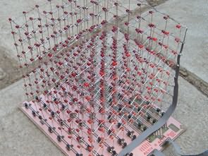
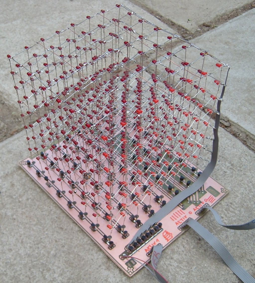
The Led Cube project was made of LED cube, one side consisted of eight LEDs, a total of 8 obsahuje = 512 LEDs. By multiplexing always the eight LEDs, any spatial “picture” can be made from luminous LEDs. The cube can be used for aesthetic purposes, presentations, games (eg 3D Snake), etc.
A total of 512 LEDs were needed to make the led cube. For reasons of price, red diffuse (CZK 1 / pc) was used. Furthermore, 72 PNP transistors (type BC640) and 8 NPN transistors (type BC338) were needed to drive a given eight. For simplicity, the connection is only for the 3x3x3 cube part.
With low-voltage port C, one LED row is selected, ie a total of 64 LEDs. In addition, the eight LEDs are activated with low level B via a low level. Port A switches specific diodes on the A port. The LED current is limited by the 10tory resistors that are connected to the NPN transistor collector in port A. The current through the LED is 50mA. The wiring allows the use of 5V DC power. It is therefore necessary to do a total of 8×8 = 64 bars to display the general image. The refresh rate is 60Hz, with no diode flicker.
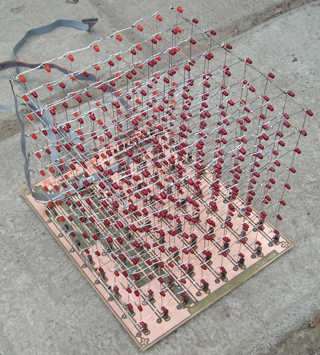
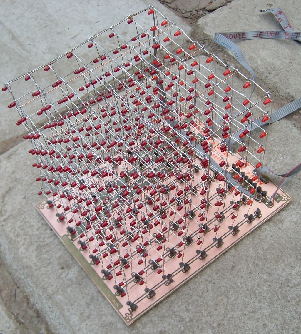
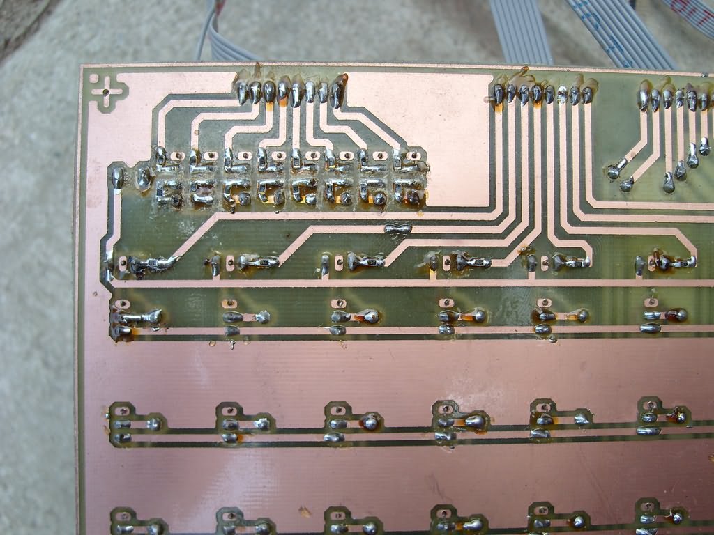
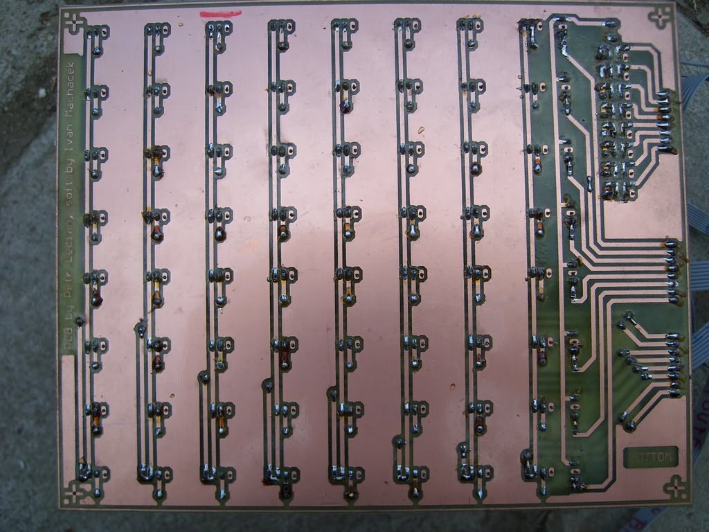
The led cube was made mechanically according to instructions. The layers were made on a plywood template, the layers were held together by a printed circuit board and wires soldered on the sides of the cube. The whole cube is solid enough. PCBs had to be implemented as double-sided. The transistors were used in a plastic case with wire outlets (TO92). Connections between PCB layers were realized by means of wire outlets. NPN transistors were selected BC338, PNP are BC640. The connection to the led cube control circuit is carried out by three flat cables. The documentation for production can be downloaded here.
The led cube control is provided by the AVR ATMEGA16 microcontroller. The ATMEGA16 16MHz clock signal is from a crystal oscillator. The cube occupies a total of 3 microcontroller ports. Using a pair of multiplexers it would be possible to control the cube ports B and C with only one microcontroller port.
ATMEGA16 Program memory: Save images to microcontroller memory.
Peripherals: 8-bit counter / timer 0 for displaying and switching images.
Switching between visualizations: A utility for checking three buttons.
Save images to microcontroller memory Due to the size of the images 64B, it is necessary to store everything in the program memory of the microprocessor, which in the case of ATMEGA16 is 16kB. The basic element is visualization, which is a group of any number of consecutive images.
The led cube is controlled by three buttons: Start / Stop, Next (NEXT) and Previous (PREV). The Start / Stop button switches between the initial visualization (eg visualization number) and the actual visualization. Use the Next and Previous buttons to select the appropriate visualization. Checking the status of the buttons is included in an infinite loop in the main part of the program. The key contacts are software-treated. Pressing the button changes the voltage level of the pin from high to low.
The created led cube is fully functional, the used microcontroller is fully sufficient, the program memory allows to record about 200 pictures. With image refresh is not a problem, LED flashing is not visible. Unfortunately, the LEDs used do not have high luminosity and are not clear. In direct daylight, it is hard to tell whether the LED is lit or not; Another continuation of the project could be connecting a dice to a PC, using EEPROM to store custom animations, simple games such as 3D Snake, etc.

FILE DOWNLOAD LINK LIST (in TXT format): LINKS-26233.zip


Circuit de cube à LED ATMEGA16
Le projet Led Cube était fait de cube LED, un côté était composé de huit LED, un total de 8 obsahuje = 512 LED. En multiplexant toujours les huit LED, toute «image» spatiale peut être réalisée à partir de LED lumineuses. Le cube peut être utilisé à des fins esthétiques, des présentations, des jeux (par exemple 3D Snake), etc.
Un total de 512 LED était nécessaire pour fabriquer le cube led. Pour des raisons de prix, du rouge diffus (1 CZK / pc) a été utilisé. De plus, 72 transistors PNP (type BC640) et 8 transistors NPN (type BC338) étaient nécessaires pour piloter un huit donné. Par souci de simplicité, la connexion est uniquement pour la partie cube 3x3x3.
Avec le port basse tension C, une rangée de LED est sélectionnée, soit un total de 64 LED. De plus, les huit LED sont activées avec un niveau bas B via un niveau bas. Le port A commute des diodes spécifiques sur le port A. Le courant de la LED est limité par les résistances de 10 étages qui sont connectées au collecteur de transistor NPN dans le port A. Le courant à travers la LED est de 50 mA. Le câblage permet l’utilisation d’une alimentation 5V DC. Il faut donc faire un total de 8 × 8 = 64 barres pour afficher l’image générale. Le taux de rafraîchissement est de 60 Hz, sans scintillement de diode.