DMX interface. These were mainly receivers and transmitters, as well as devices enabling the development of DMX networks. When running prototypes or large installations, you will definitely need a DMX scanner that can provide invaluable services. Recommendations: the scanner will be useful to people dealing with technical equipment on stage, technical setting of events, etc.
The scanner enables imaging of DMX frames without registering them or remembering them for the purpose of analyzing what is happening in the network of devices. On-off DMX signal modes are imaged as well as on / off-line USB connections that are automatically detected. The scanner can be powered from a 230 VAC network or USB port. The galvanic isolation of the scanner from the computer is ensured.
Schematic diagram of the DMX scanner
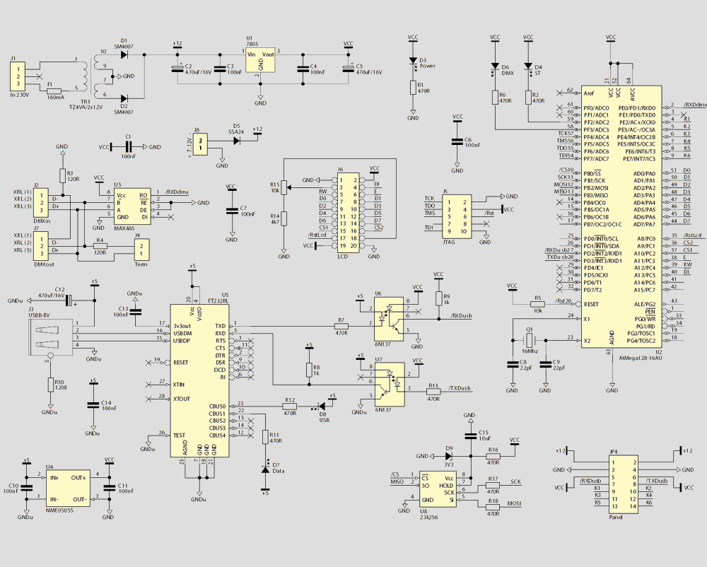
Several blocks can be distinguished in its construction: power supply, DMX-UART converter, USB-UART converter, control ATmega128 microcontroller and optional elements such as graphic display and keyboard.
The voltage is reduced from 230VAC to 12VAC by a transformer TR1 (2×12V) supplying two voltages of 12V. Then this voltage is rectified by diodes D1 and D2. After stabilization with U1 (with accompanying elements), the scanner circuits are supplied with +5 V.
The scanner can also be powered from the host computer’s USB port. In this situation, DC/DC converter (U4 NME0505S) provides galvanic isolation. If isolation is not needed, instead of U4 you can solder jumpers containing pins 1-3 and 2-4. Then you do not need to install a U1 backfeed protection diode, this is unlikely to happen during normal operation.
The J8 connector is intended for further expansion. There will be a battery connected to power the scanner in stand-alone mode. The DMX-UART converter was made based on the U3 system, C1 capacitor and resistors R3, R4. The U3 chip is a popular TTL level converter for RS485 differential transmission. It is not recommended to use the 75176 system in its place, but other substitutes may be used, e.g. AD485.
The USB-UART converter is a typical FT232RL application and galvanic isolation using U6 and U7 circuits. Due to the relatively high transmission speed (currently 38400 in newer versions of 500 kb / s software), you must not use typical optocouplers that are too slow. It is necessary to use telecommunications optocouplers with Schmitt gates.
The JP4 connector is intended for connecting a keyboard. J6 connector and resistors R15, R14 and capacitor C7 allow you to connect the LCD display.
Operating the scanner from the terminal is not convenient, that’s why the DMX Scanner v1 program was created, the window of which is shown in Figure 6. The program automatically detects the scanner attached to the computer. There is a number of information on the top bar.
From the left: information on the status of the FTDI system and two buttons, the left of which allows you to “freeze” the screen, and the right changes the way the information from the buffer is displayed. Above the buttons there is information about the status of DMX communication in the scanner. On the right side of the beam there is information about the authors and the distributor.
![]()
FILE DOWNLOAD LINK LIST (in TXT format): LINKS-26355.zip


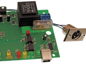
Scanner DMX ATmega128
Interface DMX. Il s’agissait principalement de récepteurs et d’émetteurs, ainsi que d’appareils permettant le développement de réseaux DMX. Lorsque vous exécutez des prototypes ou de grandes installations, vous aurez certainement besoin d’un scanner DMX qui peut fournir des services inestimables. Recommandations: le scanner sera utile aux personnes chargées du matériel technique sur scène, du cadre technique des événements, etc.
Le scanner permet d’imager des images DMX sans les enregistrer ni les mémoriser afin d’analyser ce qui se passe dans le réseau d’appareils. Les modes de signal DMX on-off sont imagés ainsi que les connexions USB on / off-line qui sont automatiquement détectées. Le scanner peut être alimenté à partir d’un réseau 230 VAC ou d’un port USB. L’isolement galvanique du scanner de l’ordinateur est assuré.
Schéma de principe du scanner DMX