The highest sound level amplifier volume, output to limit the amplifier to protect both audio bazul to prevent may be required this system in china goods 5.1 sound systems I’ve seen though they supplies full power under because they use these limitations have used, but whatever 🙂
System operation is simple amplifier from the output voltage is rectified transistor is controlled by the voltage level according to the led light is giving and LED across on the audio input connected to the chassis LDR represent the light level increases, the resistance is reduced so that the source audio signal falls, the sound and blinking naturally anf the output of the decreases in the circuit considered in making LDR to be anywhere other than the light from the LEDs in it to take the heat shrink sleeves or used black tape used

| Amp Power (8 ohm) | Peak Voltage | R3 |
| 20 W | 17 V | 820 R / 0.5 W |
| 50 W | 28 V | 1.5 k / 1 W |
| 100 W | 40 V | 1.8 k / 1 W |
| 200 W | 56 V | 2.7 k / 2 W |
| 500 W | 90V | 4.7 k / 2 W |
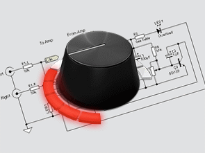
Example LDR LED layout;

Audio Amp Output Power Limiter If you hire out audio equipment, or just don’t want the kids to blow up your speakers when you are not home, this is the project for you. It is a very simple little project, but will protect the speakers from being overdriven. Any attempt at overdrive will simply cut the amp gain back – the more overdrive, the more the input signal is reduced.
This is a simple peak limiter – performance is quite respectable, and it can be used with conventional amps using bipolar transistors, MOSFETs, valves, etc, as well as BTL (Bridge Tied Load) amplifiers in car audio systems or for hi-fi. It will work with any amplifier from about 10W up to the highest power you are likely to encounter.
source: sound.westhost.com/project53.htm


Audio Spectrum Analyzer Circuit 400Led
Previously I shared 40 led vu meter circuit using Audio Spectrum Analyzer, Spectrum Analyzer circuit 10 channels (32Hz, 1kHz, 2kHz, 4kHz, 8kHz, 16kHz, 64Hz, 125Hz, 250Hz, 500Hz) on a total of 400 LED’s Spectrum Analyzer circuit 12v DC voltage works with all LEDs illuminated power draws 7.5 amps LM324 op amp used for all integrated control card and vu meter card belonging to the scheme eagle pcb files there .
Begrenzerschaltung für den Ausgang des Verstärkers
Der höchste Lautstärkepegel Lautstärke, Ausgang, um den Verstärker zu begrenzen, um beide Audio Bazul zu verhindern, kann dieses System in China Waren 5.1 Sound-Systeme, die ich gesehen habe, obwohl sie volle Leistung unter, weil sie diese Einschränkungen verwendet haben verwendet, aber was auch immer benötigt werden 🙂
Systembetrieb ist einfacher Verstärker von der Ausgangsspannung ist gleichgerichtet Transistor wird durch den Spannungspegel gesteuert, der LED-Licht gibt und LED über den Audioeingang, der mit dem Chassis LDR verbunden ist, das Lichtniveau erhöht, wird der Widerstand verringert, damit das Audio-Signal fällt, der Ton und blinkt natürlich und die Ausgabe der Abnahmen in der Schaltung berücksichtigt LDR zu einem anderen Ort als das Licht von den LEDs in es zu nehmen, die Schrumpfschläuche oder verwendete schwarze Band verwendet