Prepared by: Ahmed Saykal – Subbass filter circuit based on TL072 opamp not only more complex, integrated and a few passive components prepared with 5.1 sound system a lot, but to be effective in certain circuits of this type are used. Sub-bass filter circuit symmetrical +12 volt supply and l7912 l7812-12volt regulator with an integrated circuit made rbesl.

Sub-Bass Filter Circuit TL072 TL072A TL072B

■ Wide common-mode (up to VCC +) and differential voltage range
■ Low input bias and offset current
■ Low noise en = 15 nV/√Hz (typ)
■ Output short-circuit protection
■ High input impedance JFET input stage
■ Low harmonic distortion: 0.01% (typical)
■ Internal frequency compensation
■ Latch-up free operation
■ High slew rate: 16 V/μs (typ)
The TL072, TL072A and TL072B are high speed JFET input dual operational amplifiers incorporating well matched, high voltage JFET and bipolar transistors in a monolithic integrated circuit.
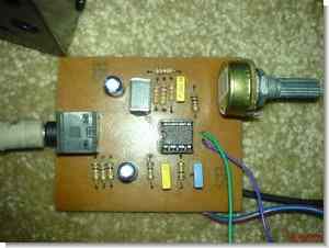
Of the control circuit and power supply PCB drawings are prepared by Proteus ares files:


PIC16C620 DC to DC Converter Circuit SMPS
Dc to dc converter circuit based on the powerful but pleasing formulas given all the details about the project is the original microchip application notes. pic16c620 Source code flow diagramm AMS assembly area and it’s a lot more information
DC DC Converter Circuitt